GFORCE: Aerodynamic Modeling
This routine models the aerodynamic forces and moments which act on a vehicle. Aerodynamics modeling provides the sensitivities of a particular vehicle to wind gusts. This program requires wind tunnel aerodynamic coefficient data for the vehicle being modeled and they must be taken according to SAE J1594 conventions for Vehicle Aerodynamics Terminology.
The user is provided an option of using two wind force points of application or only one. This option depends on the source and type of wind tunnel data. Europe tends to require two points where data in the U.S. is typically resolves to a single point. To apply aerodynamic forces at two positions on the body, the GFORCE statement described below must be duplicated at both points.
A wind velocity and angle SPLINES allow the modeler to simulate wind fans, chaotic wind forces and so on. The wind properties can be dependent on distance (useful for wind fan modeling) or on time (which allows to user to more easily investigate vehicle sensitivity versus speed). The wind velocity and angle are with respect to ground. The routine calculates relative wind speed and direction based on vehicle velocity and yaw angle.
The aerodynamic GFORCE statement takes the following form:
GFORCE/id, I=imrkr, JFLOAT=jmrkr, RM=bm_sae ,
,FUN = USER ( 1102,tarea,twb,rho,dscale,dragid,sforid,liftid,rollid, pitid,yawid,itype,windv,winda,imark)
,FUN = USER ( 1102,tarea,twb,rho,dscale,dragid,sforid,liftid,rollid, pitid,yawid,itype,windv,winda,imark)
where:
tarea | = | vehicle section frontal area value used in testing (m**2) |
twb | = | vehicle wheelbase used in testing (m) |
rho | = | density of air = 1.22 kg/mm**3 |
dscale | = | scale factor on distance to convert into meters (that is, if units are in mm, dscale = 0.001) |
dragid | = | SPLINE id of drag coefficients (set to zero for no drag force) |
sforid | = | SPLINE id of sideforce coefficients (set to zero for no side force) |
liftid | = | SPLINE id of lift coefficients (set to zero for no lift force) |
rollid | = | SPLINE id of roll coefficients (set to zero for no roll moment) |
pitid | = | SPLINE id of pitch coefficients (set to zero for no pitch moment) |
yawid | = | SPLINE id of yaw coefficients (set to zero for no yaw moment) |
itype | = | flag indicating the independent variable for the wind velocity and angle SPLINES if itype > 0 wind velocity and angle are a function of time if itype < 0 wind velocity and angle are a function of longitudinal distance in global ground X direction |
windv | = | wind velocity if windv > 0 value of "windv" denotes constant wind speed (m/s) if windv < 0 absolute value of "windv" is the id of the wind velocity SPLINE (m/s) in which the X value is time if "itype" > 0 or distance if "itype" < 0 |
winda | = | wind angle of attack (sign convention is 0 deg for straight ahead, 90 deg for wind from the right, -90 for wind from left and so on.) if winda > 0 value of "winda" denotes constant wind angle (deg). if winda < 0 absolute value of "winda" is the id of the wind angle SPLINE (deg) in which the X value is time if "itype" > 0 or distance if "itype" < 0 Note: To use a negative wind angle, it will be required to define the wind angle spline with negative wind angle values. Negative constant values are not supported. |
imark | = | MARKER id of the point of application of the forces and moments. This marker must be orientated in SAE coordinates (X out front, Y to right, and Z pointing down) |
The force application MARKER, "imark", must be in vehicle SAE orientation. The origin of this MARKER must coincide with the location at which the coefficients were measured (or be placed at the location to which the coefficients were resolved).
As a general note, the force consistency factor is test section area of the vehicle and the moment consistency factor is the test area * wheelbase. These factors must be properly passed to accurately represent the forces and moments.
The following is an example of the aerodynamics GFORCE in a vehicle model:
GFORCE/28,I=5131,JFLOAT=0131,RM=5130,
,FUN=USER(1102,2.687000,3.086,1.220000,0.001,
,106,107,108,109,110,111,-1,-201,20.00,5131)
SPLINE/201 SPLINE FOR WIND VELOCITY
,X = -10000.00, 0.00, 25000.00,
, 26000.00, 50000.00, 100000.00,
, 101000.00, 150000.00, 1000000.00
,Y = 0.00, 0.00, 0.00
, 15645.00, 15645.00, 15645.00
, 0.00, 0.00, 0.00
ARRAY/999,NUM=-2.458720e+04
SPLINE/106 SPLINE DRAG Cd
, X = -20, -15, -10, -5, 0, 5, 10, 15, 20
, Y = 0.536, 0.516, 0.481, 0.443, 0.417, 0.437, 0.476, 0.503, 0.519
SPLINE/107 SPLINE SIDE FORCE Cs
, X = -20, -15, -10, -5, 0, 5, 10, 15, 20
, Y = -1.007, -0.757, -0.506, -0.240, 0.019, 0.269,0.523,0.771, 1.008
SPLINE/108 SPLINE LIFT Cl
, X = -20, -15, -10, -5, 0, 5, 10, 15, 20
, Y = 0.517, 0.384, 0.218, 0.103, 0.066, 0.116, 0.232, 0.385, 0.513
SPLINE/109 SPLINE ROLL MOMENT Crm
, X = -20, -15, -10, -5, 0, 5, 10, 15, 20
, Y = -0.297, -0.220, -0.143, -0.068, 0.004, 0.075,0.148, 0.222, 0.295
SPLINE/110 SPLINE PITCH MOMENT Cpm
, X = -20, -15, -10, -5, 0, 5, 10, 15, 20
, Y = 0.106, 0.093, 0.096, 0.109, 0.112, 0.106, 0.098, 0.097, 0.109
SPLINE/111 SPLINE YAW MOMENT Cym
, X = -20, -15, -10, -5, 0, 5, 10, 15, 20
, Y = -0.079, -0.067, -0.050, -0.021, 0.009, 0.037, 0.063, 0.078, 0.08
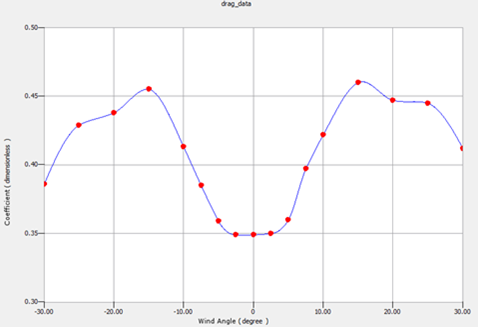
Figure 17 Example 2D spline for Drag Coefficient
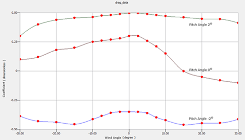
Figure 18 Example 3D spline for Drag Coefficient