Modelling Rack Pinion Steering in ACar using AMachinery Gear
You can replace 'coupler' type steering gear with 'machinery gear' using this method.
Disable existing pinion to rack gear
1. Open _rack_pinion_steering.tpl.
2. Disable the grsred_pinion_to_rack which will be replaced by machinery gear.
Create Pinion
1. Select Build → AMachinery Gear → Cylindrical Gear → Cylindrical Gear Element → New.
The Create Cylindrical Gear Element dialog box appears.
2. Enter the values as listed below in the dialog box.
a. Rack gain for one revolution of pinion:
≈ 360o pinion rotation
= 36.0004mm rack displacement
b. Assumptions:
Normal module = 1.55
Normal pitch of pinion = ?*1.55 = 4.87mm
(for better contact ratio with less number of teeth)
Assumed Helix angle on pinion = 20o
Transverse pitch of pinion = 4.87/cos(20)
= 5.18mm
c. Number of teeth on pinion
= rack_gain/ Transverse pinion pitch
= 36.004/5.18 = 6.94 = 7
To avoid interference due to lesser (seven) number of teeth, it is necessary to use profile modification on pinion.
d. Refer to rps_pinion.gea from machinery_examples.cdb/gear_elements.tbl as property file.
e. Select cfs_pinion_pivot as construction frame for pinion.
f. Choose connection as fixed joint with ges_pinion from connections tab.
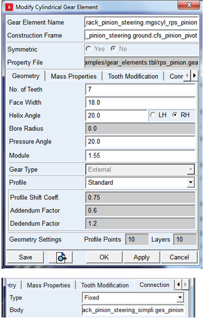
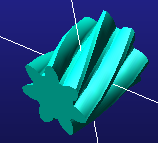
3. Click OK. The completed pinion model will be displayed as below:
Find Rack placement
1. Pinion number of teeth 7 and module 1.55
2. Pinion PCD is 7*1.55 = 10.85
3. Transverse pitch diameter of pinion = 10.85/cos(20) = 11.54mm
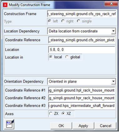
4. Hence rack location from is 11.54/2 ≈ 5.8mm
5. Rack orientation should be same as existing 'ges_rack'
6. Create a construction frame 'rps_rack_ref' with respect to pinion frame
Create Rack
Assumption:
1. Total rack gain:
Approximately 3 revolutions of pinion (or steering wheel) = 120 mm
2. Transverse Pinion Pitch = Normal Pinion Pitch / cos(helix angle)
= 4.87/cos(20) = 5.18mm
3. Total number of teeth on rack = 120/5.18 = 23
4. Refer to rps_rack.gea in machinery_examples.cdb/gear_elements.tbl
5. Select cfs_prs_rack_ref as construction frame created in step 3.
6. Choose connection as fixed with ges_rack
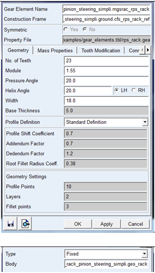
7. Select OK.
The completed rack model will be displayed as below:

Create gear force
1. Select gear type Simplified or 3D from menu:
2. Select Build → AMachinery Gear → Rack Gear → Simplified Rack Gear Force → New
3. Select property file rack_simplified_gear_force from machinery_examples/gear_stiffness.tbl
4. Select rack and pinion gear elements created in step 2 and 3.
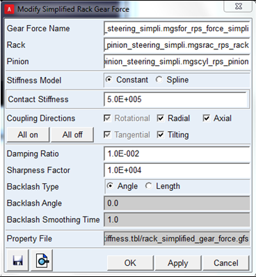
5. Click OK.
Alternatively you can select '3D gear force', if required formulation is '3D'.
1. Save Template
2. Create TR_steering subsystem
1. Switch to standard mode.
2. Open TR_Steering subsystem and click yes to use existing _rack_pinion_steering template.
3. Visually inspect rack and pinion if they are meshing correctly without interference.
4. Save TR_steering subsystem.
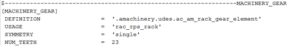
5. Open the TR_steering subsystem to check if 'MACHINERY_GEAR' block is correctly reflected for rack, pinion and force elements.

1. Create MDI_FRONT_STEERING subsystem
With _rack_pinion_steering created in step-6 in session, open MDI_FRONT_STEERING subsystem and click ‘yes’ to use existing '_rack_pinion_steering' template.
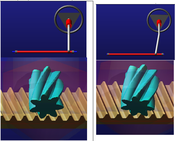
Note: | Visually inspect the rack and pinion for correct mesh. The rack and pinion are not meshing correctly in MDI_FRONT_STEERING as the construction frame of pinion (cfs_pinion_pivot) is changed as mentioned below: |
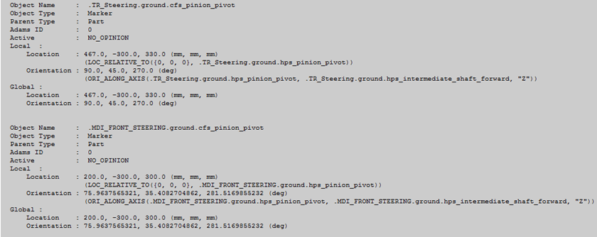
Note the difference of angle between MDI and TR steering subsystems for cfs_pinion_pivot:
1. 45(TR) - 35.4082704862 (MDI)= 9.5917295138
2. Adjust the helix angle of rack by opening the rack gear element in subsystem mode
3. Reduce the helix angle of rack by '9.5917295138 deg'
4. (20-9.5917295138= 10.408deg)
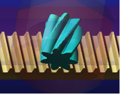
Note: | Visually inspect resulting mesh as shown in the figure. |
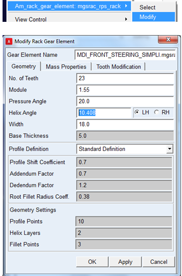
5. Click OK.
The completed model will be displayed as below:
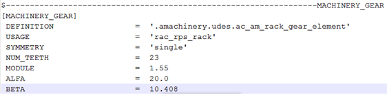
6. Save MDI_Steering Subsystem and check the helix angle (BETA) is modified correctly in subsystem file (in respective MACHINERY_GEAR block)
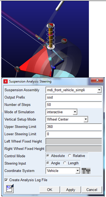
1. Run Analysis
1. Open mdi_front_vehicle.asy using newly created _rack_pinion_steering and (or select mdi_front_vehicle_simpli.asy from 'machinery_example.cdb' )
2. Run 'steering' analysis for one complete revolution of steering wheel (3600)
3. Open mdi_front_vehicle.asy using standard assembly file in acar_shared_database and run 'steering' analysis for one complete revolution of steering wheel (3600)
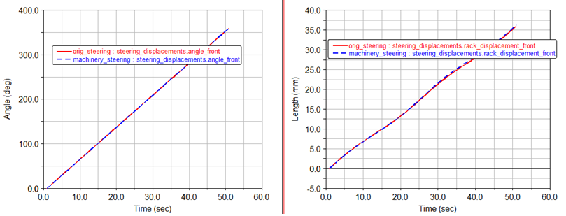
4. Compare results for 'rack displacement'.
5. Rack Displacement
Machinery Gear = 36.2733mm for one revolution of steering wheel
acar_shared_database = 36.004mm for one revolution of steering wheel