Adding the vertical setup mode of Adams Car Suspension Testrig
This example demonstrates the use of the MDI_SUSPENSION_TESTRIG for quasi-static suspension analysis. The vertical mode named "VERTICAL_MODE_FOR_SETUP" in the loadcase file is added to the suspension testrig. "VERTICAL_MODE_FOR_SETUP" means the vertical control method at time=0. This allows you to set the vertical mode method at both the setup phase (time=0) and the simulation phase.
This is very important for models including adjustable forces. Because when you correlates with test data, it is important to match the physical initial condition setup with that of the simulation.
Model Description
A Suspension Assembly consisting of a double wishbone suspension including adjustable force and a rack and pinion steering system is provided. We carry out quasi-static suspension analysis with two setup mode for vertical control. One is "wheel_center_height". Other is "contact_patch_height. And we then plot the toe angle in order to make sure the differences. | 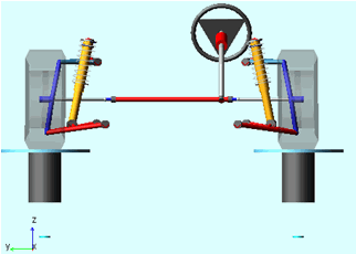 |
Performing the analysis in order to investigate the vertical setup mode.
Here you first analyze a double wishbone suspension including adjustable force.
1. Start Adams, select Standard Interface.
2. Create a new Suspension assembly: File → New → Suspension Assembly. Fill the dialog box as indicated below. To select the subsystems, Right click → Search → <acar_shared> to open the file browser.
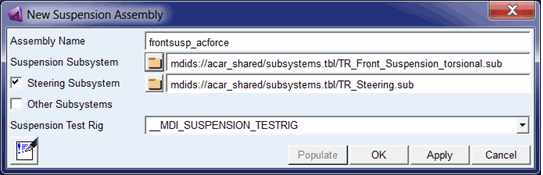
3. The suspension assembly should be displayed.
4. Go to Adjust - Adjustable Force. And select ".frontsusp_acforce.TR_Front_Suspension_torsional.afl_toe_adjustment" for the "Adjustable Force" field. Then you can see the desired value (-0.5). This value means that the toe angle is adjusted to -0.5 at setup phase.
5. Go to Simulate → Suspension Analysis → Parallel Wheel Travel…and click on Alignment Button.
Note: | Tip text will display the name of adjustable force. |
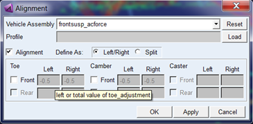
6. Click "Front" toggle button under "Toe" which will activate adjustable force ".frontsusp_acforce.TR_Front_Suspension_torsional.afl_toe_adjustment".
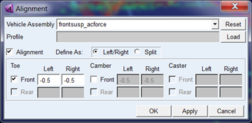
Now you can see the desired value (-0.5). This value means that the toe angle is adjusted to -0.5 at setup phase.
Click OK.
7. Set up the analysis as follows. In this case, the vertical travel of the wheel is controlled to keep 0 mm in setup phase.
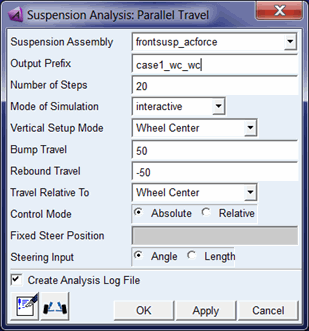
8. Select OK.
9. Go to Simulate → Suspension Analysis → Parallel Wheel Travel… again
10. Set up the analysis as follows for the second analysis. In this case, the vertical travel of the contact patch is controlled to keep 0mm in setup phase.
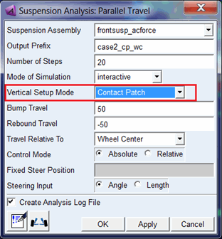
11. Select OK.
Note: | "Absolute" at "Control Mode" means that the vertical displacement is controlled the displacement with absolute value. "Relative" means that the displacement is relative to the position at the setup phase. |
Review the results
Plot the toe angle in two analyses:
1. Press the F8 key in Adams Car to switch to Adams PostProcessor.
2. From the simulation list, select the two analyses.
3. From the right of the dashboard, set Independent Axis to Data. (The Independent Axis Browser appears. You perform the next four steps in the browser.)
4. From the Request list, select wheel travel. You might have to scroll down to see this entry.
5. From the Component list, select vertical_left.
6. Select OK.
7. Locate the testrig.toe_angle REQUEST under user-defined REQUESTs. And select left in component list.
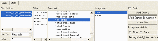
8. Select Add curve. You can see the plot of wheel_travel vs toe_angle.
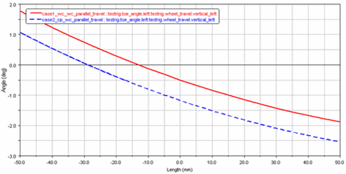
The toe angle in Red line(case1...) should be -0.5 by adjustable force when wheel_travel is 0.
9. Create New page.
10. From the right of the dashboard, set Independent Axis to Data. And select jfl_jack_force_data in request list and displacement in component list.
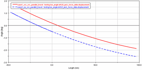
11. Plot the toe angle again. You can see the plot of contact_patch_height vs toe_angle.
The toe angle in Blue line(case2...) should be -0.5 by adjustable force when contact_patch_height is 0.
Remarks
■"VERTICAL_SETUP_MODE" is available with all quasi-static suspension analysis. When you create the loadcase file, the setup mode is described as follows in loadcase file.
[MODE]
STEERING_MODE = 'angle'
$ wheel_center_height/ contact_patch_height
VERTICAL_MODE_FOR_SETUP = 'contact_patch_height'
VERTICAL_MODE = 'wheel_center_height'
VERTICAL_TYPE = 'absolute'
COORDINATE_SYSTEM = 'vehicle'
■"Control Mode" is also described as follows in loadcase file.
[MODE]
STEERING_MODE = 'angle'
$ wheel_center_height/ contact_patch_height
VERTICAL_MODE_FOR_SETUP = 'contact_patch_height'
VERTICAL_MODE = 'wheel_center_height'
VERTICAL_TYPE = 'absolute'
COORDINATE_SYSTEM = 'vehicle'