Controlling Geometry Visibility
This example demonstrates how you can control the visibility of parts and individual part geometries at the subsystem level.
1. In the Template Builder, open the template mdids://acar_shared/templates.tbl/_rigid_chassis.tpl.
2. In the Model Browser, select the Groups tab. Right-click on the chassis_outline group and hit Modify. The group is defined as shown below:
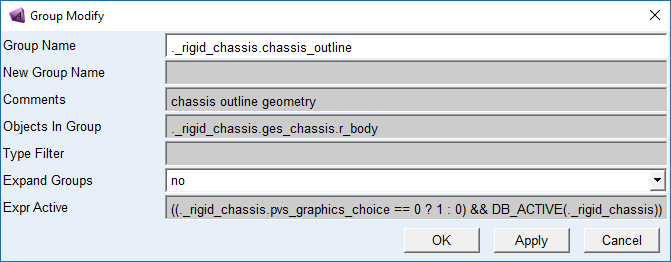
This group contains one of the geometry children of the chassis part. Its activity (and therefore its visibility) is controlled by a parameter variable named "pvs_graphics_choice". The activity expressions says, if this variable is 0, the outline will be active.
3. In the Model Browser, right-click on the chassis_graphics_1 group and hit Modify. The group is defined as shown below:
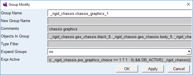
This group contains most of the other geometry children of the chassis part. Its activity expression says if the pvs_graphics_choice is 1, these geometries will be active.
4. Close the template and switch to the Standard Interface,
5. Open the subsystem mdids://acar_shared/subsystems.tbl/TR_Body.sub
6. Modify the Parameter Variable pvs_graphics_choice. Set its value to 0 and hit Apply. The CAD geometry is hidden and the outline geometry is displayed.
7. Right-click on the part ges_chassis and select Hide. Note that the outline and the ellipsoid are now invisible, but the inertia_frame marker is still visible. If you were to save the subsystem at this point, you'd see the following lines in the .sub file:
[PART_ASSEMBLY]
USAGE = 'chassis'
SYMMETRY = 'single'
MODE = 'rigid'
DISPLAY_GRAPHICS = 'no'
…
[PARAMETER]
{parameter_name symmetry type value}
'graphics_choice ' 'single ' 'integer' 0