Gear Element: Hypoid Gear
(Template Builder) Build → Gears → AMachinery Gear → Hypoid Gear → Hypoid Gear Element New/Modify
For the option: | Do the following: |
|---|---|
Element Name | ■Pinion ■Wheel |
If Pinion is selected as element name then following options displayed: | |
Pinion Name | Enter the name for the Pinion. |
Select Wheel | Select the wheel from the options. |
Hypoid Offset | Pinion ref. marker is located and orientated relative to the wheel ref. marker. ■Location: a distance a (=hypoid offset) along with the positive y-axis of the wheel reference marker, see below. A positive hypoid offset means therefore a positive value on wheel ref. marker y-axis. Vice versa for a negative hypoid offset value. ■Orientation: z-axis of pinion ref. marker is parallel and pointing to the same direction as the x-axis of the wheel ref. marker. 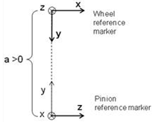 Enter the Pinion offset (absolute value): ■If spiral angle of wheel is right and pinion is left, the hypoid offset is set to a positive value. ■If spiral angle of wheel is left and pinion is right, the hypoid offset is set to a negative value. Location orientation of pinion is auto calculated. (The calculated values can be seen in modify mode or database navigator). For given wheel location-orientation, only unique pinion location orientation exists. Hence, 'new-existing' option is disabled for this type. All other spatial orientation of hypoid gear set can be obtained by appropriately specifying the orientation of wheel-ref_marker. |
Symmetric | ■Yes ■No |
Property File | |
Geometry Tab | |
Pressure Angle Single | Enter a nominal pressure angle in current modelling Units (default value = 20.0 deg) expressed in the normal plane. For the hypoid gear this angle is the angle between a vertical line and the tooth profile at the datum line. |
Pressure Angle Dual | ■Concave ■Convex |
No. of Teeth | Enter the number of teeth (threads) for the hypoid gear element and Worm Wheel. |
Face Width | Enter the face width for Pinion and Wheel. |
Back Distance | Enter the distance between the tip circle on back cone and the back plane (only used for graphic). Measured along gear axis. It can be calculated as below: Back Distance = Mounting Distance - Crown to Crossing Point (t_xo) distance |
Pitch Angle | This defines the angle (delta) of the pitch cone, which is the angle between gear axis and a pitch cone envelope line. It is also known as Reference Cone Angle. |
Pitch Apex | Enter the distance (t_z) between pitch cone apex and the crossing point, measured along gear axis. Positive value if pitch cone apex is located beyond the crossing point. |
Bore Radius | Enter the radius for the hole in the Pinion and Wheel (only used for graphics). |
Mean Spiral Angle | Enter the helix angle (beta_m) at the mean cone distance (and at pitch circle). |
LH/RH | Select if the Helix Angle should be Left Hand (LH) or Right Hand (RH). The choice decides the sign of the Helix Angle (Left Hand of gear 1 = Positive). |
Choose between entering value for Outer Cone Distance, Outer Transversal Module, Mean Cone Distance or Mean Normal Module: | |
Outer Cone Distance | Enter the distance (R_e) from pitch cone apex to the outer end of the teeths measured along the pitch cone envelope line. |
Outer Trans. Module | Enter the value for transversal module (m_et) at the end of the teeth. |
Mean Cone Distance | Enter the distance (R_m) from pitch cone apex to the middle of the face width measured along the pitch cone envelope line. |
Mean Normal Module | Enter the normal (R_m) module at the middle of the face width. |
Tooth Depth and Width | Select the "Data Type" format option which describes the gear dimensions (tooth depth and width) at Mean Cone Distance according to ISO 23509 - 2006. "Data Type I" is used in European standards while "Data Type II" format is used in AGMA standards. ■Data Type I - ISO 23509 ■Data Type II - ISO 23509 |
If Data Type I - ISO 23509 is selected, the following options will be displayed: | |
Profile Shift Coeff. | Enter a value for profile shift coefficient (x_hm) for the gear (positive or negative value). Default value = 0.0. If this field is left blank, no profile shifting will be used. |
Addendum Factor | Enter a value for the addendum factor (k_hap) (default value = 1.0). It is used together with the profile shift coefficient (x_hm) to calculate the height (h_am, mean addendum) by which the gear tooth projects above the pitch cone at mean cone distance. h_am = m_mn * (k_hap + x_hm) |
Dedendum Factor | Enter a value for the dedendum factor (k_hfp) (default value = 1.25). It is used together with the profile shift coefficient to calculate the depth (h_fm, mean dedendum) of the tooth space below the pitch cone at mean cone distance. h_fm = m_mn * (k_hfp - x_hm) |
Thickness Mod. Coeff. | Enter a value for the tooth modification coefficient (x_sm). It is used to calculate the mean normal circular tooth thickness (s_mn) and it should include the backlash. s_mn = m_mn * (0.5 * pi +2* (x_sm+x_hm * tan (alfa_n)) |
If Data Type II - ISO 23509 profile is selected, the following options will be displayed: | |
Mean Addendum Factor | Enter a value for mean addendum factor (c_ham) (default value=0.5). Used together with depth factor (k_d) to calculate the height (h_am, mean addendum) by which the gear tooth projects above the pitch cone. h_am = c_ham * k_d * m_mn. |
Depth Factor | Enter a value for depth factor (k_d) (default value = 2.0). It is used to calculate tooth addendum (h_am), working depth (h_mw) and clearance (c_m). h_am = c_ham * k_d * m_mn h_mw = k_d * m_mn c_m = k_d * k_c * m_mn |
Clearance Factor | Enter a value for the clearance factor (k_c) (default value = 0.125) which is used for calculating tooth clearance (c_m). c_m = k_d * k_c *m_mn Where m_mn is the normal module at mean cone distance. |
Thickness Factor | Enter a value for the thickness factor (k_t) which is used to calculate the mean normal circular tooth thickness (s_mn). It is related to the Thickness Modification Coefficient, see below: k_t= 2 * x_sm |
Geometry Settings | ■Number of Profile Points Defines the number of points for the half tooth profile (the other half is mirrored). Default value is 10 points. Note: Number of Profile Points in hypoid geometry will have influence only if tip relief is used and this parameter is not used if you only have crowning. ■Number of Helix Layers Defines the number of "layers" of the gear width should be divided into. This number should increase with increasing helix angle and gear width. Default value is 5 layers. ■Number of Fillet Points Defines the number of points for root radius fillet. If set to 0 the fillet will become a chamfer. Default value is 3 points. |
Mass Properties Tab | |
Define Mass By | ■User Input If you do not want Adams View to calculate mass and inertia using a part's geometry, material type, or density, you can enter your own mass and moments of inertia. ■Geometry and Density You can change the material type used to calculate mass and inertia or simply specify the density of the part. ■Geometry and Material Type The geometry defines the volume and the material type defines the density. |
If you select User Input, the following options will be displayed: | |
Mass | Enter the mass of the gear part. |
The parts are located at the center of the gear, with the z-axis as the rotational axis. | |
Inertia | |
Ixx/Iyy/Izz | Enter the values that define the principal mass-inertia components of the gear part. |
Ixy/Izx/Iyz | Enter the values that define the deviational (cross-product) mass-inertia components of the gear part. |
If you select Geometry and Density, the following options will be displayed: | |
Density | Enter the density value. |
Inertia Geometry | ■ Exact Define mass by default 'density' option, Adams View uses the part's density and the volume of the geometry to calculate its mass and inertia. ■Approximate Approximate volume of the gear element is calculated based on addition of gear blank (cylinder or cone) dimension and involute thread volume. Bore volume is subtracted from this calculated volume. For cylindrical gears, the cylindrical gear blank dimension is considered whereas front and rear cone dimensions are considered in case of bevel and hypoid. Rack considers the base width and trapezoidal teeth volume. The approximately calculated volume is multiplied by density to calculate mass. Approximate method has significant gain in performance over material and exact-density options. However, the calculated values are slightly less than other methods. |
If you select Geometry and Material Type, the following options will be displayed: | |
Material Type | Enter the material type to be used inertia calculation. |
Connection Tab | |
Type | Select one of the following: ■Rotational ■Compliant ■Fixed ■None |
Rotational | The gear and attachment part is connected with revolute joint. |
Compliant | The gear and attachment part is connected with Adams Bushing. |
Fixed | The gear and attachment part is connected with fixed joint. |
None | No joint is created between gear and attachment part. You can create joint manually or put a bearing between gear and attachment part. |
Body | Enter the name of the body. |