Precompute Advanced 3D Gear Contact
(Template Builder) Build → Gears → A/Machinery Gear → Cylindrical Gear → Precompute Advanced 3D Gear Contact
For the option | Do the following |
|---|---|
Gear Contact Property File | Enter gear contact property file name. |
Gear Force | Select the propery files from the list. |
Advanced Gear Property File | Enter advanced gear contact property file name. |
Flexible Gear Property File | Enter flexible gear property file name. |
GCP Creation The below options helps you to create GCP file which contains all necessary data for precomputed contact. The data is generated automatically by a test rig. The preprocessing starts with automated building of gear pair test rig in the background. You need to provide an input for both the gears (or refer to an existing FGF to fill up GUI). 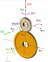 The test rig create FGP files for both the gears and uses those files for simulation with the specified excitation (radial, axial and so on.) | |
Workspace To support misalignments, you need to fill the entries in group Workspace. Misalignments are applied symmetrically, relatively to the initial position of the secondary wheel, the smaller gear in picture. | |
Radial Displacement | Radial Displ., Dist.  Enter explicitly axial distance between the gear wheels. In case the testrig is extracted from existing model the axial distance is taken from the model, for case the model is assembled manually the axial distance is suggested. For zero value the entry is ignored. Radial Displ.  Defines range for radial distance variations from initial position. The range is defined symmetrically to the initial position by value 'Perturbation' and for 'Steps' *2 + 1 discrete positions resp. -'Steps' to + 'Steps' including zero deviation. Corresponds to ITY on Figure. |
Axial Displacement | Axial Displ.  Defines range for translations in direction of rotational axis from initial position. It is assumed the initial offset between gear centers is zero. Corresponds to ITZ on Figure. |
Lateral Misalignment | Lateral Misalignment 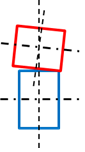 Defines range for inclination angles about x axis of contact coordinate system from initial position. Corresponds to IRX on Figure. |
Radial Misalignment | Radial Misalignment 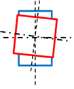 Defines range for inclination angles about y axis of contact coordinate system from initial position. Corresponds to IRY on Figure. Radial Displacement corresponds to ITY translational direction and is applied relative to actual axial distance of gears; this distance can be corrected or set in the input box left to the step entry, if zero is specified, the default axial distance is used. Axial Distance corresponds to ITZ translational direction, Lateral Misalignment corresponds to IRX rotation and Radial Misalignment corresponds to IRY rotation of secondary gear wheel. The entries in Step field effectively define Step * 2 + 1 total steps starting from - Perturbation and going to + Perturbation for every workspace dimension. |
Calculation Options | |
Number of steps/halp_pitch | Defines the discretization along the pitch angle of the primary wheel 1. During the preprocessing the gears are rotated from -wheel 1 pitch angle half to + wheel 1 pitch angle half to capture the contact at different relative positions of gear wheels. The total number of positions is equal to 'Number of steps' * 2 + 1. |
Torque | Defines maximum applied torque at every workspace position. The torque is applied in number of steps defined in entry Steps/Workspace dimensions and corresponds to IPERT rotation. If the launched preprocessor produces *.gcp file with no misalignment effects then, this can be used for simple concept studies with rigid shafts and kinematic joints. |
Steps/Workspace dimensions | Enter the number of steps. |
Inverse Mode | The toggle Inverse Mode allow you to skip free play calculations for right / minus flank and just mirror the results of left / plus flank calculations. |