Gear Element: Rack Gear
(Template Builder) Build → Gears → AMachinery Gear → Rack Gear → Rack Gear Element New/Modify
For the option: | Do the following: |
|---|---|
Gear Element Name | Enter the name of the rack gear element. |
Construction Frame | Select the reference frame for creating gear. Gear rotation axis will be aligned with 'Z' of the reference frame. |
Symmetric | ■Yes ■No |
Property File | You can reference to available property file to specify input parameters for gear and force. |
Geometry Tab | |
No. of Teeth | Enter the number of teeth (threads) for the rack gear element and Rack Wheel. |
Module | Enter the value for module. |
Pressure Angle (Normal) | Enter a nominal pressure angle in current modelling Units (default value = 20.0 deg) expressed in the normal plane. For the rack gear this angle is the angle between a vertical line and the tooth profile at the datum line. |
Helix Angle | Enter a value for the helix angle (beta) in current modelling Units. The helix angle describes how the teeth are angled from the transversal plane. |
Width | Enter the face width for Rack and Pinion in modelling units. |
Base Thickness | Enter the thickness of the base of the rack in modeling units (geometry only). The base thickness is measured from the root to the bottom of the gear part. Default value = 5mm. |
Profile Defintion | Select how the involute profile should be described using the Standard Involute Profile parameters (Profile Shifting, Addendum Factor & Dedendum Factor) or if the parameters for the Modified Involute Profile (Tip Radius, Root Radius & Tooth Thickness) should be used. ■Standard Definition ■Modified Definition |
If Standard Definition is selected, the following options will be displayed: | |
Profile Shift Coeff. | Enter a value for profile shift coefficient (Previously called addendum modification coefficient) for the gear (positive or negative value). The value decides if the datum line is to be shifted towards the top (positive) or towards the root (negative value). Default value = 0.0. If this field is left blank, no profile shifting will be used. |
Addendum Factor | Enter a value for the Addendum Factor (default value = 1.0). The Addendum Factor is used to calculate the Addendum: Addendum (Normal) = Module (Normal) * Addendum Factor |
Dedendum Factor | Enter a value for the Dedendum Factor (default value = 1.25). The Dedendum Factor is used to calculate the Dedendum: Dedendum (Normal) = Module (Normal) * Dedendum Factor |
Root Fillet Radius Coeff. | Enter a coefficient > 0 to be multiplied with the module. The resulting product will describe the root filet radius for rack. If the value is 0 no radius will be used. |
If Modified profile is selected, the following options will be displayed: | |
Tooth Height | Enter a value > 0 in length units for the Tooth Height for the rack gear. The Tooth Height is measured from the root (bottom) of the tooth profile to the tip of a tooth (top). |
Pitch Line Offset | Enter a value > 0 in length units for the offset from the tip or a tooth (top of the rack) to the Pitch line. |
Tooth Thickness (along pitch line) | Enter a value > 0 in length units for the thickness of the teeth measured in the transversal plane at the pitch line. |
Root Fillet Radius | Enter a value ≥ 0 to define the root filet radius. If the value is 0 no radius will be used. |
Geometry Settings | ■Number of Profile Points Defines the number of points for the half tooth profile (the other half is mirrored). Default value is 10 points. Note: Number of Profile Points in rack geometry will have influence only if tip relief is used and this parameter is not used if you only have crowning. ■Number of Helix Layers Defines the number of "layers" of the gear width should be divided into. This number should increase with increasing helix angle and gear width. Default value is 5 layers. ■Number of Fillet Points Defines the number of points for root radius fillet. If set to 0 the fillet will become a chamfer. Default value is 3 points. |
Mass Properties Tab | |
Define Mass By | ■User Input If you do not want Adams View to calculate mass and inertia using a part's geometry, material type, or density, you can enter your own mass and moments of inertia. ■Geometry and Density You can change the material type used to calculate mass and inertia or simply specify the density of the part. ■Geometry and Material Type The geometry defines the volume and the material type defines the density. |
If you select User Input, the following options will be displayed: | |
Mass | Enter the mass of the gear part. |
The parts are located at the center of the gear, with the z-axis as the rotational axis. | |
Inertia | |
Ixx/Iyy/Izz | Enter the values that define the principal mass-inertia components of the gear part. |
Ixy/Izx/Iyz | Enter the values that define the deviational (cross-product) mass-inertia components of the gear part. |
If you select Geometry and Density, the following options will be displayed: | |
Density | Enter the density value. |
Inertia Geometry | ■ Exact Define mass by default 'density' option, Adams View uses the part's density and the volume of the geometry to calculate its mass and inertia. ■Approximate Approximate volume of the gear element is calculated based on addition of gear blank (cylinder or cone) dimension and involute thread volume. Bore volume is subtracted from this calculated volume. For cylindrical gears, the cylindrical gear blank dimension is considered whereas front and rear cone dimensions are considered in case of bevel and hypoid. Rack considers the base width and trapezoidal teeth volume. The approximately calculated volume is multiplied by density to calculate mass. Approximate method has significant gain in performance over material and exact-density options. However, the calculated values are slightly less than other methods. |
If you select Geometry and Material Type, the following options will be displayed: | |
Material Type | Enter the material type to be used inertia calculation. |
Tooth Modification Tab | |
Tip Relief Start | Tip relief is a modification of a tooth profile whereby a small amount of material is removed near the tip of the gear tooth. 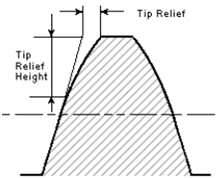 The Tip Relief Start parameter defines the position on the tooth at which the Tip Relief will start. The resulting starting radius on the gear will be: Start Radius = Tip Radius - Tip Relief Start * Module (Transverse) The Module (Transverse), MT is defined as below: MT = MN / cos(ß) If the gear is defined by Standard Involute Profile, the Tip Radius is defined as below: Tip Radius = 0.5 * MT * Z + MT * (Addendum Factor + Profile Shift Coefficient) Note: Default value is 0.0. The limit is 0.0 -1.0. |
Tip Relief Coefficient | This coefficient defines the maximum Tip Relief reached at the Tip Radius of the gear. The Tip Relief is defined by: Tip Relief = Tip Relief Coefficient * MT The tip relief will have zero value at the Tip Relief Start point and increase linearly out to the Tip Radius. Note: Default value is 0.0. The limit is 0.0 -1.0. |
Crown Magnitude | Crowning is the removal of a slight amount of tooth from the center on out to reach edge, making the tooth surface slightly convex. This method allows the gear to maintain contact in the central region of the tooth and permits avoidance of edge contact with consequent lower load capacity. Crowning also allows a greater tolerance in the misalignment of gears in their assembly, maintaining central contact. 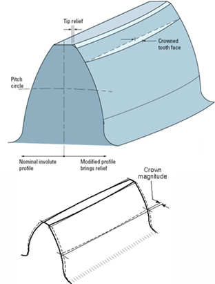 The crown magnitude is reached at the edges of the tooth and crowning is zero at the center of the tooth. The crowning is described as an arc. The Crown Magnitude is entered in length units. Note: Crowning magnitude is dependent on width of gear and is a non-negative value. |
Connection Tab | |
Type | Select one of the following: ■Rotational ■Compliant ■Fixed ■None |
Rotational | The gear and attachment part is connected with revolute joint. |
Compliant | The gear and attachment part is connected with Adams Bushing. |
Fixed | The gear and attachment part is connected with fixed joint. |
None | No joint is created between gear and attachment part. You can create joint manually or put a bearing between gear and attachment part. |
Body | Enter the name of the body. |