Bevel / Hypoid Gear
In current release you can define a bevel or hypoid gear tooth profile by processing of CAD geometry only. This approach is valid only in case that the CAD data represent true shape of the tooth. In case you would like to perform study of microgeometry influence on the system dynamics the CAD data should not include microgeometry modifications. To extract tooth profile from CAD geometry you need to input essential dimensions of the gear in the shape definition step of Gear AT preprocessing which are stored in so called definition file (*.hgd file). After Shape definition processing is finished all relevant geometrical data including profile are stored in a hypoid gear property file (*.hgp) which is used as input for meshing and for bevel/hypoid gear element definition. Next step is to generate FE meshes then run Nastran SOL 101 and extract stiffness matrix to a hypoid gear stiffness file (*.hgs), which is then used for gear force definition.
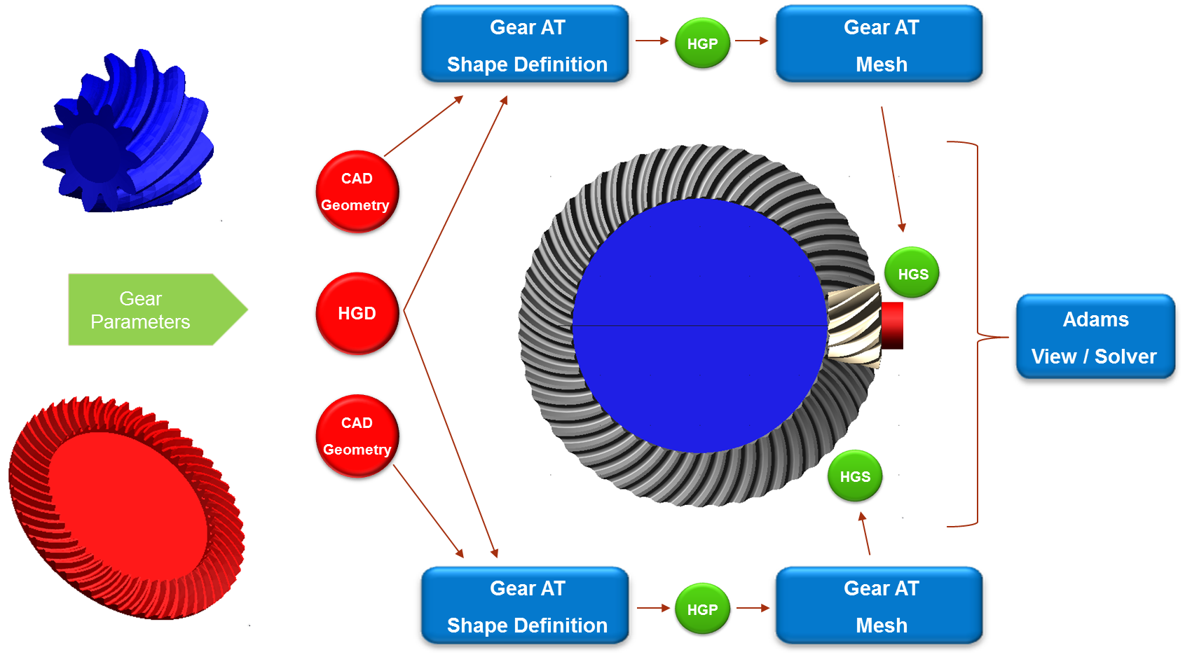
Figure 234 Hypoid / Bevel Gear dataflow