Involute Spline Joint
In Gear AT one can define internal and external involute spline gears. In current release you can define a tooth profile from scratch using only final machining tool. The first step is to input all gear parameters in the shape definition step of Gear AT preprocessing which stores all geometrical data including profile in an involute spline property file (*.isp) which is used as input for meshing and for involute spline gear element definition. Next step is to generate FE meshes, run Nastran SOL 101 and extract stiffness matrix to an involute spline stiffness file (*.iss), which is then used for spline joint force definition. There are essential geometrical involute spline data stored in definition file (*.isd) to define machining tools for later use, so it can be used as input file in Shape Definition dialog box.
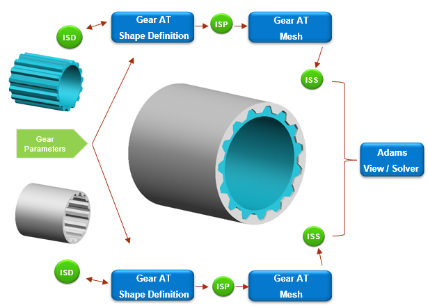
Figure 358 Involute Spline Joint data flow