Create Sprocket - Geometry-Guide
Machinery → Create Sprocket
For the option | Do the following |
|---|---|
Number of Guides | Enter the value based on number of guides to be created. Note: The maximum number of guides allowed is 10. |
Type | ■Fixed ■Pivot ■Translational |
If you select Fixed type, the following options will be displayed: | |
Guide | |
Guide1 | Enter the guide name. |
Center Location | Enter the location coordinates or pick. |
Axis of Rotation | ■Orientation ■Pick (Marker) ■Global Z ■Global X ■Global Y |
Geometry | |
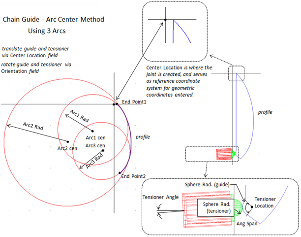
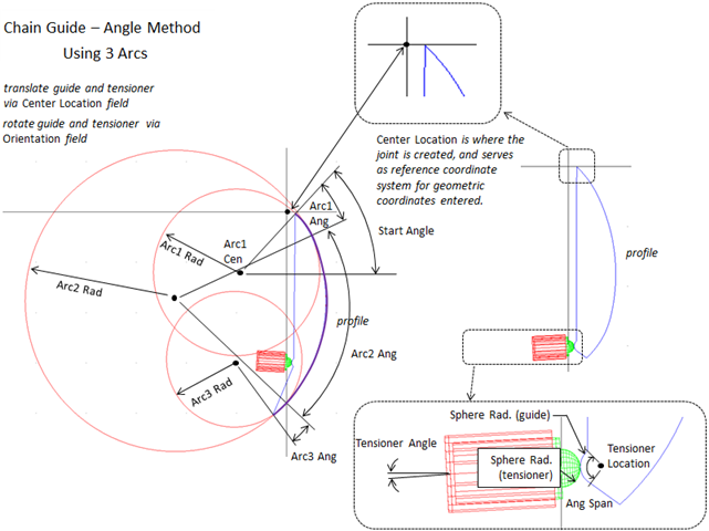
Type | Select one of the following: ■Center Points - Allows you to specify the end points of the whole profile and each arc's center point. ■Angles - Allows you to specify the center point of the first arc and each arc's angle. |
If you select Center Points type, the following options will be displayed: The contact surface geometry of the guide is defined by up to five arcs. You specify the start and end points for the outline formed by the arcs. Two sequential arcs must intersect and tangent. The end points must exist on the first and last arc radii, respectively. Specify all locations relative to the guide's reference frame (coordinate reference). Define the arcs in a clockwise direction around the z-axis. | |
Guide Width | Enter the width of the guide part. |
Number of Arcs | Select the number of arcs you want to specify for the guide geometry. Adams Machinery displays an equal number of Arc# Radius and Arc# Center text boxes where you can define the radius and center of the arcs. |
End Point1 | Enter the end point of the first arc. The point must exist on the radius of the first arc. |
End Point2 | Enter the end point of the last arc. The point must exist on the radius of the last arc. |
Arc1/2/3 Rad. | Enter the arc1/2/3 rad. |
Arc1 Cen. | Enter the center location relative to the attach coordinate reference. |
If you select Angles type, the following options will be displayed: The contact surface geometry of the guide is defined by up to five arcs. You specify the start of the first arc by defining a radius, a location and an angle relative to the attach coordinate reference. You define the subsequent arcs by specifying a radii and an angle. Specify all locations relative to the guide's reference frame (coordinate reference). Define the arcs in a clockwise direction around the z-axis. | |
Guide Width | Enter the width of the guide part. |
Number of Arcs | Select the number of arcs you want to specify for the guide geometry. Adams Machinery displays enough Arc# Radius and Arc# Center text boxes where you can define the radius and center of the arcs. |
Start Angle | Enter the angle relative to the x-axis of the attached coordinate reference that defines the start point of the first arc. |
Arc1/2/3 Cen. | Enter the center location of the first arc relative to the attached coordinate reference. |
Arc1/2/3 Rad. | Enter the arc1/2/3 radius. |
Arc1/2/3 Ang. | Enter the angle that defines the length of the arc. Note: Enter only positive values. |
Tensioner | |
Angle | Enter the angle of the tensioner attach marker. To align the z-axis of the tensioner attach marker with the positive x-axis of ref_marker, enter 0.0. |
Location | Enter the location of the tensioner attach marker. Specify only x and y values relative to ref_marker. |
Sphere Rad. | Radius of the tensioner's hemi-spherical tip that contacts the guide. A zero indicates a flat surface. |
Ang. Span | Enter the angle span. |
If you select Translational/Pivot type, the following options will be displayed: ■Pivot Guide: A Pivot Guide is a part constrained with a rotational joint. You can use a pivot guide with a chain. ■Translational Guide: A Translational Guide is a part constrained with a translational joint. You can use a translational guide with a chain. ■Fixed Guide: A Fixed Guide is a part constrained with fixed joint. You can use a fixed guide with a chain. | |
Tappet Creates or modifies a Spring-Damper Tappet. Defining the Tappet The following force function defines the tappet: f = (dm + Free Length - Installed Length)*-Stiffness + vr*-Damping where: ■dm - Displacement ■vr - Velocity | |
Tappet | ■spd ■Stiffness ■Enter the stiffness of the tappet. ■Damping ■Enter the damping of the tappet. The damping is in force units * time units/length units. ■nli ■Spring File ♦Select a file for the tappet stiffness. ■Damping File ♦Select a file for the tappet damping. |
Guide Connection | Specify the part to which the guide is to be connected. |
Housing Connection | ■ Yes ■Specify the part to which the housing is to be connected. ■No ■No joint is created between housing and attachment part. You can create joint manually between housing and attachment part. |