Create Sprocket - Roller
Machinery → Create Sprocket
For the option | Do the following |
|---|---|
If you select Constraint method, the following options will be displayed: | |
Number of sprockets | Enter the number of sprockets to be created. Note: The maximum number of sprockets allowed per model is 50. The maximum number of sprockets allowed per sprocket set is 15. |
Axis of Rotation | ■Orientation ■Pick (Marker) ■Global Z ■Global X ■Global Y |
Sprocket 1/2/.. | |
Sprocket Name | Enter the sprocket name. In modify mode, click in this field and press the Enter/Return key to highlight the sprocket within the graphics window. |
Center Location | Enter the location coordinates or pick. |
Geometry | |
Sprocket Width | Enter the sprocket width. |
Sprocket Diameter. | Enter the sprocket diameter. |
If you select 2D/3D Links and 3D Links Nonplanar method, the following options will be displayed: | |
Number of sprockets | Enter the value based on number of sprockets to be created. Note: The maximum number of sprockets allowed per model is 50. The maximum number of sprockets allowed per sprocket set is 15. |
Axis of Rotation | ■Orientation ■Pick (Marker) ■Global Z ■Global X ■Global Y |
Sprocket 1/2.. | |
Sprocket Name | Enter the sprocket name. In modify mode, click in this field and press the Enter/Return key to highlight the sprocket within the graphics window. |
Center Location | Enter the location coordinates or pick. |
Angular Mis-Alignment (X) | Enter pulley misalignment around X in angle units Note: This parameter is available only for 3D Links Nonplanar |
Angular Mis-Alignment (Y) | Enter pulley misalignment around Y in angle units Note: This parameter is available only for 3D Links Nonplanar |
Geometry | |
Sprocket Width | Enter the width of the sprocket wheel. |
Number of Teeth | Enter the number of teeth on the sprocket. Note: The maximum number of teeth allowed is 100. |
Profile Method | Select one of the following: ■Parameters - Specify all parameters to define the geometry. ■ISO 606 - Geometry is defined by the number of teeth and the parameters of the chain. ■Outline - Define the outline by specifying pitch diameter and angle and radius values. |
If you select Parameters profile, the following options will be displayed: | |
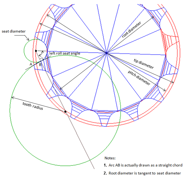
Pitch Diameter | Enter the pitch diameter. The pitch diameter defines the center of the seat radii. |
Root Diameter | Enter the root diameter. |
Seat Radius | Enter the radius of the seat. |
Tip Diameter | Enter the tip diameter. |
Left Tooth | |
Radius | Enter the radius of the left tooth flank. |
Roll Seat Angle | Enter the left angle of the contact between roller and seat. The angle defines the point to the left of the seat center, where the seat radius and the left tooth radius are tangent. |
Right Tooth | |
Radius | Enter the radius of the right tooth flank. |
Roll Seat Angle | Enter the right angle of the contact between roller and seat. The angle defines the point to the right of the seat center, where the seat radius and the right tooth radius are tangent. |
In/Out Chain | Select if the sprocket should be inside or outside the wrapped chain. ■In ■Out |
If you select ISO 606 profile, the following options will be displayed: | |
In/Out Chain | Select if the sprocket should be inside or outside the wrapped chain. ■In ■Out |
If you select Outline profile, the following options will be displayed: | |
Pitch Diameter | Enter the pitch diameter. The pitch diameter defines the center of the seat radii. |
Radius and Angle | Click the Data Editor/Viewer to enter points to define the outline of a tooth. Each point is defined by an angle and a radius relative to the sprocket center. The points must be sorted by increasing angle. |
In/Out Chain | Select if the sprocket should be inside or outside the wrapped chain. ■In ■Out |