Create Sprocket - Silent
Machinery → Create Sprocket
For the option | Do the following |
|---|---|
If you select Constraint method, the following options will be displayed: | |
Number of sprockets | Enter the number of sprockets to be created. Note: The maximum number of sprockets allowed per model is 50. The maximum number of sprockets allowed per sprocket set is 15. |
Axis of Rotation | ■Orientation ■Pick (Marker) ■Global Z ■Global X ■Global Y |
Sprocket 1/2/.. | |
Sprocket Name | Enter the sprocket name. In modify mode, click in this field and press the Enter/Return key to highlight the sprocket within the graphics window. |
Center Location | Enter the location coordinates or pick. |
Geometry | |
Sprocket Width | Enter the sprocket width. |
Sprocket Diameter | Enter the sprocket diameter. |
If you select 2D/3D Links method, the following options will be displayed: | |
Number of sprockets | Enter the value based on number of sprockets to be created. Note: The maximum number of sprockets allowed per model is 50. The maximum number of sprockets allowed per sprocket set is 15. |
Axis of Rotation | ■Orientation ■Pick (Marker.) ■Global Z ■Global X ■Global Y |
Sprocket 1/2.. | |
Sprocket Name | Enter the sprocket name. In modify mode, click in this field and press the Enter/Return key to highlight the sprocket within the graphics window. |
Center | |
Location | Enter the location coordinates or pick. |
Geometry | |
Sprocket Width | Specify the width of the sprocket wheel. |
Number of Teeth | Specify the number of teeth on the sprocket. Note: The maximum number of teeth allowed is 100. |
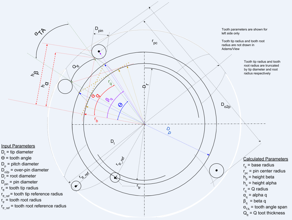
Pitch Diameter | Enter the pitch diameter of the involute sprocket. |
Root Diameter | Enter the root diameter of the involute sprocket. |
Tip Diameter | Enter the tip diameter of the involute sprocket. |
Tooth Angle | Enter the tooth angle for the sprocket. This angle is also referred to as the pressure angle. It is used to specify the tooth profile which is based on the involute function. |
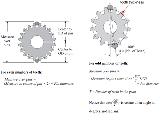
Over Pin Diameter | Enter the diameter specifying the thickness of the sprocket teeth according to the "Over 2 Pin Diameter" measurement. |
Pin Diameter | Enter the diameter of the pin used for the Over 2 Pin Diameter measurement.  |
Left Tooth | |
Tip Radius | Enter the radius of the left tooth tip flank. |
Tip Ref Radius | Enter the distance from the sprocket center to the center of the left tooth tip radius. |
Root Radius | Enter the radius of the left tooth root flank. |
Root Ref Radius | Enter the distance from the sprocket center to the center of the left tooth root radius. |
Right Tooth | |
Tip Radius | Enter the radius of the right tooth tip flank. |
Tip Ref Radius | Enter the distance from the sprocket center to the center of the right tooth tip radius. |
Root Radius | Enter the radius of the right tooth root flank. |
Root Ref Radius | Enter the distance from the sprocket center to the center of the right tooth root radius. |
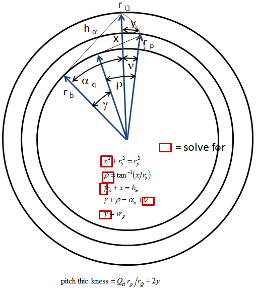
Notes on tooth dimension calculations
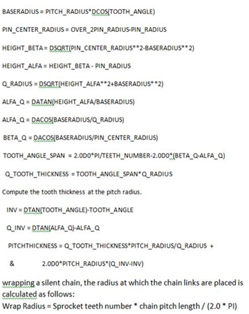
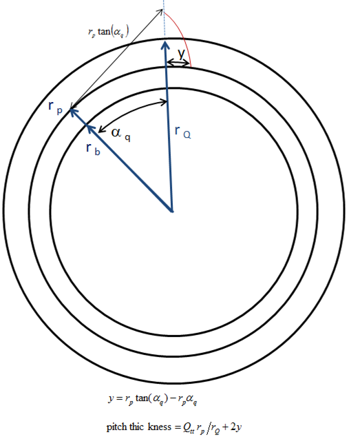
“Exact” method to calculate additional tooth width at pitch radius
“Approximate” method used in Adams Machinery to calculate additional tooth width at pitch radius