Create Cam Profile
Machinery → Create Cam Profile
For the option | Do the following |
|---|---|
Cam Details | |
Profile Name | Enter the cam profile name. The name of the cam profile that is being created is auto generated. The user may edit it if required. |
Cam Shape | Select the cam shape from the list. ■Disk ■Cylindrical(Barrel) ■Single Sided Grooved |
Minimum Radius/Cam Radius | Enter the minimum radius of the cam (also known as the "base radius"). ■Minimum Radius - Disk Cams ■Uncut/Base Radius - Cylindrical or Single Sided Grooved Cam |
Thickness/Cam Length | Enter the thickness of the cam. ■Thickness - Thickness of Disk Cams or Single Sided Grooved Cam ■Cam Length - Length of the Cylindrical Cam |
Location | Enter the location. ■Disk - Center of Base Radius and center of thickness. ■Cylinder - Center of Cam Radius and at one end of the cylinder. Other end of the cylinder will be in the negative Z direction. ■Single sided Grooved - Center of Cam radius at the groove side face. Other face of the disk will be in the negative Z direction. |
Axis of Rotation | Axis of Rotation of the cam can be defined by one of the following: ■Orientation ■Pick (Marker) ■Global Z ■Global X ■Global Y |
If you selected Cylindrical(Barrel) or Single Sided Grooved cam shape, the following options are available: | |
Groove Width | Enter the width value of the groove. Not applicable to disk type cams. This is the dimension cut on the face of the disk cam or surface of the cylindrical to form the groove. |
Groove Depth | Enter the depth value of the groove. Not applicable to disk type cams. This is the dimension cut into the disk cam along the normal to the surface to form the groove or the dimension cut radially into the cylindrical cam to form the groove. |
Follower Details | |
Follower Motion Type | ■Existing/Create - Select to create a new follower motion or a pre-existing one already created via the follower motion wizard. ■Import - Select to define the follower motion via data points in a .csv file. Example files illustrating the required format of this file can be found in "<installation_directory>\amachinery\examples\cam" |
If you select Existing/Create type, the following options are displayed in the next page of the wizard: | |
Follower Motion Name | Select the follower motion name created or use the button to open the follower motion wizard and create a follower motion. |
Follower Arrangement | ■Inline - Select if the follower axis is inline with the cam center. ■Offset - Select if the follower axis is at an offset from the cam center. ■Offset Distance - Enter the amount of offset of the follower axis from the cam center. Positive offset will move the follower along positive X direction, negative offset will move the follower along negative X direction. |
Follower Motion Type | ■Translation - Select if the follower displaces along its axis. ■Pivotal Motion - Select if the follower pivots about a point. ■Pivot offset from cam center ■X Offset - Enter the offset of the pivot point along X axis. ■Y Offset - Enter the offset of the pivot point along Y axis. 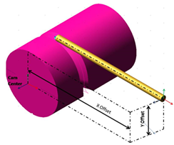 |
Follow Geometry | Select the desired type of follower Geometry: ■Knife Edge ■Circular End ■Circular End Details - Radius - Enter the radius value of Circular follower end. ■Flat Face ■Flat face Details - End width - Enter the end width value of the flat faced follower. ■Curve ■Curve Details - Radius - Enter the radius value of Curved follower end. The curve is obtained by sweeping the entered radius for 180 degree with follower arm axis as center. 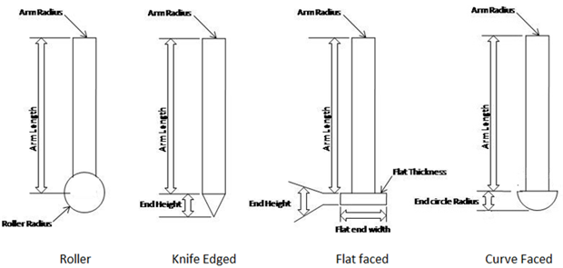 |
Offset along Cam axis | Enter the offset value of the follower starting position from the cam location face. Applicable only for Cylindrical Cam. 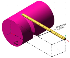 |
Offset from Cam center | Enter the offset of the Groove center to the cam center. Applicable only for Single sided grooved Cam. 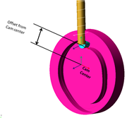 |
If you selected Import type, the following options displayed: | |
Independent Variable | ■Time - Select if the X-axis of the imported file corresponds to time. ■Cam Angle - Select if the X-axis of the imported file corresponds to cam angle. |
External File | Select the external file. 1. The .csv file should contain only 2 axes. X corresponds to time/angle. Y corresponds to displacement. 2. First and last displacement values should be zero. 3. If independent variable is angle, then the X values should start with 00 and end with 3600. Example files illustrating the required format of these files can be found in “<installation_directory>\amachinery\examples\cam” |
Follower Arrangement | ■Inline - Select if the follower axis is inline with the cam center. ■Offset - Select if the follower axis is at an offset from the cam center. ■Offset Distance - Enter the amount of offset of the follower axis from the cam center. Positive offset will move the follower along positive X direction, negative offset will move the follower along negative X direction. |
Follower Motion Type | ■Translation - Select if the follower displaces along its axis. ■Pivotal Motion - Select if the follower pivots about a point. ■Pivot offset from cam center ■X Offset - Enter the offset of the pivot point along X axis. ■Y Offset - Enter the offset of the pivot point along Y axis. 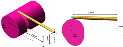 |
Follow Geometry | Select the desired type of follower Geometry: ■Knife Edge ■Circular End ■Circular End Details - Radius - Enter the radius value of Circular follower end. ■Flat Face ■Flat face Details - End width - Enter the end width value of the flat faced follower. ■Curve ■Curve Details - Radius - Enter the radius value of Curved follower end. The curve is obtained by sweeping the entered radius for 180 degree with follower arm axis as center. |
If you selected Cylindrical Cam as cam shape, the following options displayed: | |
Offset along Cam axis | Enter the offset value of the follower starting position from the Cam Location face. |
If you selected Single Sided Grooved as cam shape, the following options displayed: | |
Offset from Cam center | Enter the offset of the Groove center from the Cam center. |
Profile Points | |
The follower profile points are displayed in non-editable format. | |