Gear Output
Machinery → Gear Output
For the option | Do the following |
|---|---|
Gear Set Name | Enter the gear set name. |
Contact Forces (Simplified/Detailed). See Gear Force (spur/helical gears) for more information. | |
Total Force | Total contact force at the point of contact. |
Tangential Force | Tangential force at the point of contact. The sign convention of tangential force is based on direction of motion/torque, gear orientation and helix angle. Reversing the direction of motion will reverse the direction of tangential force. |
Torque | Torque acting in Gear 1 due to Gear contact along the rot.axis. |
Module | Gear Module. |
Number of Teeth | Number of Teeth Gear 1 and Gear 2. |
Radial Force | Radial force at the point of contact. |
Axial Force | Axial force at the point of contact. The sign convention of axial force is based on direction of motion/torque, gear orientation and helix angle. Reversing the direction of motion will reverse the direction of axial force. |
Stiffness | The local rotational stiffness. |
Damping | Damping torque portion of the backlash torque. |
Center Distance | The center distance of a pair of meshing spur gears is the sum of their pitch circle radii. One of the advantages of the involute system is that small variations in the center distance do not affect the correct working of the gears. |
Pressure Angle | The pressure angles in transverse (alfa t) and working plane (alfa w) is the angle between the line of action and the common tangent to the pitch circles at the pitch point is the pressure angle. |
Pressure Angle Dual (Hypoid) | Simplified method: This will be based on sense of rotation CW or CCW and respective concave or convex flanks contacts each other in a gear pair. The output request takes active flank in to the consideration. If the active flank is concave, then concave pressure angle is considered for force calculation and vice versa for convex flanks. The active transverse pressure angles concave or convex based on sense of rotation are shown in request as below: alfa_trans1 and alfa_trans2 will change in output request (if concave and concave/convex pressure angles are different on both gears) 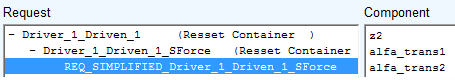 Where: alfa_trans1 = Pressure_angle_trans (gear1) = tan-1 (tan(pressure angle gear1)/cos(mean_spiral_angle)) alfa_trans2 = Pressure_angle_trans (gear2) = tan-1 (tan(pressure angle gear2)/cos(mean_spiral_angle)) The request naming convention matches with the gear force definition. For example, REQ_SIMPLIFIED_Planet_1_to_Ring is based on general force having I and J bodies as Planet_1 and Ring gear. 3D method: No pressure angle calculation is needed for force calculation. It is based on geometry and physical contact. |
Helix Angle | Helix angle at Pitch Diameter. Units expressed at the pitch circle. Note that the sign of the helix angle will decide the rotation of the helicoid (right/left). |
Angular Displacement | ■Gear1 Angular displacement of Gear 1 along the rot.axis. ■Gear 2 Angular displacement of Gear 2 along the rot.axis. |
Angular Velocity | ■Gear1 Angular velocity(Omega) of Gear 1 along the rot.axis. ■Gear 2 Angular velocity(Omega) of Gear 2 along the rot.axis. |