Bevel Gear
Creates or modifies a bevel gear element. More information about bevel gear terminology can be found here.
Bevel gear | |
|---|---|
For the option | Do the following |
If Simplified method is selected, the following options will be displayed: | |
Pressure Angle (Normal Plane) | Enter a nominal pressure angle (alfa_n) (default value = 20.0 deg) expressed in the normal plane. It is specified at the mean cone distance. The angle between the line of action and the common tangent to the pitch circles at the pitch point is the pressure angle. |
Mean Spiral Angle | Enter the helix angle (beta_m) at the mean cone distance (and at pitch circle). |
Center Location | Enter the coordinates or Pick (Markers, View location and so on.) |
GEAR PAIR | |
Name | Enter the name of the Gear 1 and Gear 2. ■New ■Existing: Use the Select Gear options to load the existing gear. |
Axis of Rotation | Axis of Rotation of Gear 1 and Gear 2 can be one of the following: ■Orientation ■Pick (Marker) ■Global Z ■Global X ■Global Y |
No. of Teeth | Enter the number of teeth (Z) for Gear 1/Gear 2. |
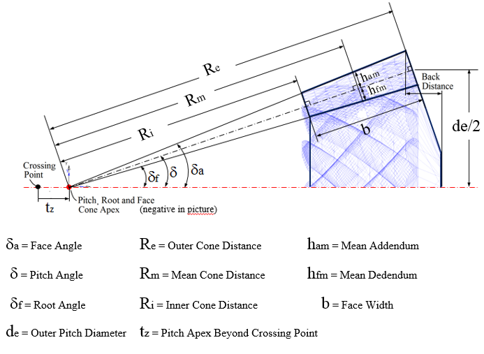
Face Width | Enter the width (b) of the tooth face of Gear 1 and Gear 2. |
Back cone distance | Enter the distance between the tip circle on back cone and the back plane (only used for graphic). Measured along gear axis. It can be calculated as below: Back Distance = Mounting Distance - Crown to Crossing Point (t_xo) distance. 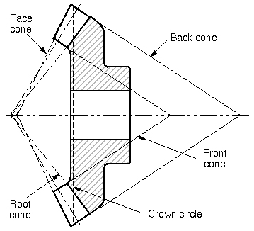 |
Pitch Angle | This defines the angle (delta) of the pitch cone, which is the angle between gear axis and a pitch cone envelope line. It is also known as Reference Cone Angle. |
Pitch Apex | Enter the distance (t_z) between pitch cone apex and the crossing point, measured along gear axis. Positive value if pitch cone apex is located beyond the crossing point. |
Bore Radius | Enter the radius for the hole in the gear 1 and gear 2 (only used for graphics). |
Hand of Helix | ■LH/RH Select if the Helix Angle should be Left Hand (LH) or Right Hand (RH). The choice decides the sign of the Helix Angle (Left Hand of gear 1 = Positive). |
Choose between entering value for Outer Cone Distance, Outer Transversal Module, Mean Cone Distance or Mean Normal Module: | |
Outer Cone Distance | Enter the distance (R_e) from pitch cone apex to the outer end of the teeths measured along the pitch cone envelope line. |
Outer Trans. Module | Enter the value for transversal module (m_et) at the end of the teeth. |
Mean Cone Distance | Enter the distance (R_m) from pitch cone apex to the middle of the face width measured along the pitch cone envelope line. |
Mean Normal Module | Enter the normal (R_m) module at the middle of the face width. |
Geometry Settings | ■Number of Profile Points Defines the number of points for the half tooth profile (the other half is mirrored) through which a curve is fit. ■Number of Helix layers Defines the number of "layers" of the helical gear width should be divided into. This number should increase with increasing helix angle and gear width. For helix angle equal to 0 degrees (spur gear) this value will be automatically set to 2, otherwise the value specified in this field is used. Note: Increasing this value may improve resolution of geometry especially for wider gears but at the expense of increased time to create gear pair. |
If 3D Contact method is selected, the following options will be displayed: | |
Pressure Angle (Normal Plane) | Enter a nominal pressure angle (alfa_n) (default value = 20.0 deg) expressed in the normal plane. It is specified at the mean cone distance. The angle between the line of action and the common tangent to the pitch circles at the pitch point is the pressure angle. |
Center Location | Enter the coordinates or Pick (Markers, View location and so on.) |
GEAR PAIR | |
Name | Enter the Gear 1 and Gear 2 name. ■New ■Existing: Use the Select Gear options to load the existing gear. |
Axis of Rotation | Axis of Rotation of Gear 1 and Gear 2 can be one of the following: ■Orientation ■Pick (Marker) ■Global Z ■Global X ■Global Y |
No. of Teeth | Enter the number of teeth (Z) for Gear 1/Gear 2. |
Face Width | Enter the face width for Gear 1 and Gear 2 (used only for graphics). |
Back cone distance | Enter the distance between the tip circle on back cone and the back plane (only used for graphic). Measured along gear axis. It can be calculated as below: Back Distance = Mounting Distance - Crown to Crossing Point (t_xo) distance. |
Pitch Angle | This defines the angle (delta) of the pitch cone, which is the angle between gear axis and a pitch cone envelope line. It is also known as Reference Cone Angle. |
Pitch Apex | Enter the distance (t_z) between pitch cone apex and the crossing point, measured along gear axis. Positive value if pitch cone apex is located beyond the crossing point. |
Bore Radius | Enter the radius for the hole. |
Choose between entering value for Outer Cone Distance, Outer Transversal Module, Mean Cone Distance or Mean Normal Module: | |
Outer Cone Distance | Enter the distance (R_e) from pitch cone apex to the outer end of the teeths measured along the pitch cone envelope line. |
Outer Trans. Module | Enter the value for transversal module (m_et) at the end of the teeth. |
Mean Cone Distance | Enter the distance (R_m) from pitch cone apex to the middle of the face width measured along the pitch cone envelope line. |
Mean Normal Module | Enter the normal (R_m) module at the middle of the face width. |
Mean Spiral Angle | Enter the helix angle (beta_m) at the mean cone distance (and at pitch circle). |
Hand of Helix | ■LH/RH Select if the Helix Angle should be Left Hand (LH) or Right Hand (RH). The choice decides the sign of the Helix Angle (Left Hand of gear 1 = Positive). |
Tooth Depth and Width | Select the "Data Type" format option which describes the gear dimensions (tooth depth and width) at Mean Cone Distance according to ISO 23509 - 2006. "Data Type 1" is used in European standards while "Data Type 2" format is used in AGMA standards. ■Data Type 1 - ISO 23509 ■Data Type 2 - ISO 23509 |
If Data Type I - ISO 23509 is selected, the following options will be displayed: | |
Profile Shift Coefficient | Enter a value for profile shift coefficient (x_hm) for the gear (positive or negative value). Default value = 0.0. If this field is left blank, no profile shifting will be used. |
Addendum Factor | Enter a value for the addendum factor (k_hap) (default value = 1.0). It is used together with the profile shift coefficient (x_hm) to calculate the height (h_am, mean addendum) by which the gear tooth projects above the pitch cone at mean cone distance. h_am = m_mn * (k_hap + x_hm) where m_mn is the normal module at mean cone distance. |
Dedendum Factor | Enter a value for the dedendum factor (k_hfp) (default value = 1.25). It is used together with the profile shift coefficient to calculate the depth (h_fm, mean dedendum) of the tooth space below the pitch cone at mean cone distance. h_fm = m_mn * (k_hfp - x_hm) where m_mn is the normal module at mean cone distance. |
Thickness Modification Coefficient | Enter a value for the tooth modification coefficient (x_sm). It is used to calculate the mean normal circular tooth thickness (s_mn) and it should include the backlash. s_mn = m_mn * (0.5 * pi +2* (x_sm+x_hm * tan (alfa_n)) where m_mn is the normal module at mean cone distance. |
If Data Type II - ISO 23509 is selected, the following options will be displayed: | |
Mean Addendum Factor | Enter a value for mean addendum factor (c_ham) (default value=0.5). Used together with depth factor (k_d) to calculate the height (h_am, mean addendum) by which the gear tooth projects above the pitch cone. h_am = c_ham * k_d * m_mn. where m_mn is the normal module at mean cone distance. |
Depth Factor | Enter a value for depth factor (k_d) (default value = 2.0). It is used to calculate tooth addendum (h_am), working depth (h_mw) and clearance (c_m). h_am = c_ham * k_d * m_mn h_mw = k_d * m_mn c_m = k_d * k_c * m_mn where m_mn is the normal module at mean cone distance. |
Clearance Factor | Enter a value for the clearance factor (k_c) (default value = 0.125) which is used for calculating tooth clearance (c_m). c_m = k_d * k_c *m_mn where m_mn is the normal module at mean cone distance. |
Thickness Factor | Enter a value for the thickness factor (k_t) which is used to calculate the mean normal circular tooth thickness (s_mn). It is related to the Thickness Modification Coefficient, see below: k_t= 2 * x_sm |
Geometry Settings | ■Number of Profile Points Defines the number of points for the half tooth profile (the other half is mirrored) through which a curve is fit. ■Number of Helix layers Defines the number of "layers" of the helical gear width should be divided into. This number should increase with increasing helix angle and gear width. For helix angle equal to 0 degrees (spur gear) this value will be automatically set to 2, otherwise the value specified in this field is used. Note: Increasing this value may improve resolution of geometry especially for wider gears but at the expense of increased time to create gear pair. |