Hypoid Gear
Creates or modifies a hypoid gear element. More information about hypoid gear terminology can be found here.
Hypoid gear | |
|---|---|
For the option | Do the following |
If Simplified method is selected, the following options will be displayed: | |
Pressure Angle Single | The pressure angle is the angle between the line of action and the common tangent to the pitch circles at the pitch point is the pressure angle. Enter a real value that defines the gear pressure angle. |
Presure Angle Dual | Enter a real value for the Concave and Convex angle. 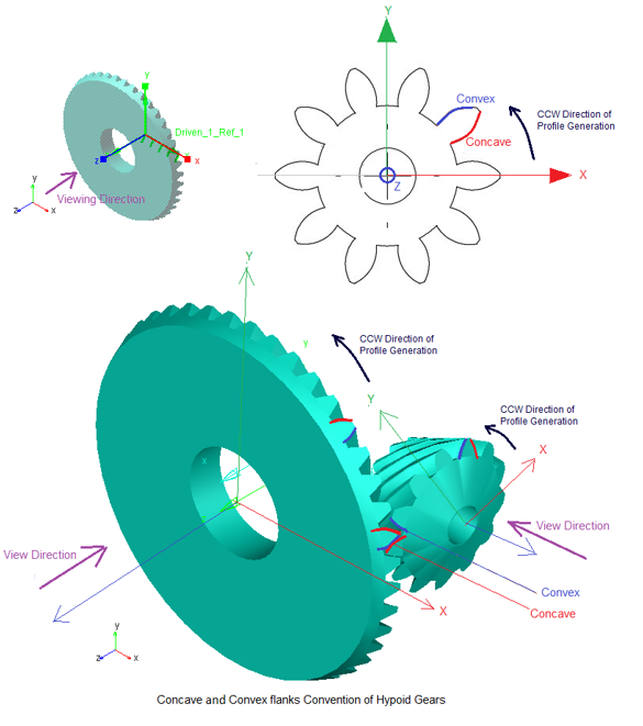 This will be based on sense of rotation CW or CCW and respective concave or convex flanks contacts each other in a gear pair. The output request takes active flanks in to the consideration. If the active concave-convex flank pair is considered for force calculation. |
Pinion and Wheel | |
Name | Enter the name of the Pinion and Wheel. ■New ■Existing: Use the Select Gear options to load the existing gear. |
Axis of Rotation | Axis of Rotation of Wheel can be one of the following: ■Orientation ■Pick (Marker) ■Global Z ■Global X ■Global Y Note: Orientation of pinion is auto calculated. |
Center Location | Enter the coordinates or Pick (Markers, View location and so on.) Note: Location of pinion is auto calculated. |
Hypoid Offset | Pinion ref. marker is located and orientated relative to the wheel ref. marker. ■Location: a distance a (=hypoid offset) along with the positive y-axis of the wheel reference marker, see below. A positive hypoid offset means therefore a positive value on wheel ref. marker y-axis. Vice versa for a negative hypoid offset value. ■Orientation: z-axis of pinion ref. marker is parallel and pointing to the same direction as the x-axis of the wheel ref. marker. 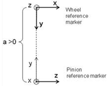 Enter the Pinion offset (absolute value): ■If spiral angle of wheel is right and pinion is left, the hypoid offset is set to a positive value. ■If spiral angle of wheel is left and pinion is right, the hypoid offset is set to a negative value. Location orientation of pinion is auto calculated. (The calculated values can be seen in modify mode or database navigator). For given wheel location-orientation, only unique pinion location orientation exists. Hence, 'new-existing' option is disabled for this type. All other spatial orientation of hypoid gear set can be obtained by appropriately specifying the orientation of wheel-ref_marker. |
No. of Teeth | Enter the number of teeth for Pinion and Wheel. |
Face Width | Enter the face width for Pinion and Wheel. |
Bore Radius | Enter the radius for the hole in the Pinion and Wheel (only used for graphics). |
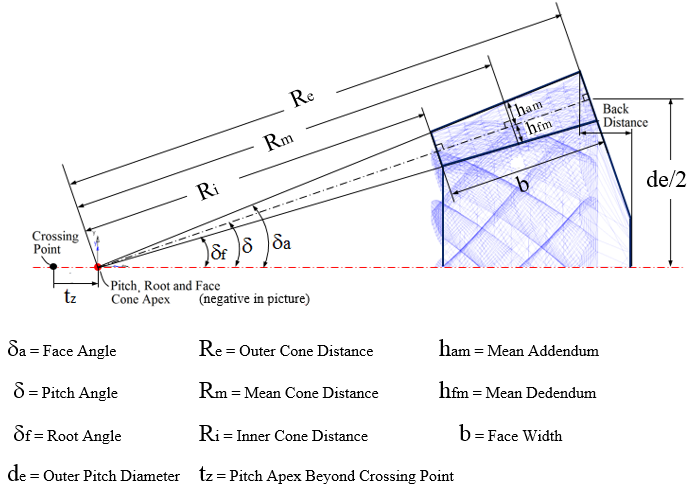
Pitch Angle | This defines the angle (delta) of the pitch cone, which is the angle between gear axis and a pitch cone envelope line. It is also known as Reference Cone Angle. |
Pitch Apex | Enter the distance (t_z) between pitch cone apex and the crossing point, measured along gear axis. Positive value if pitch cone apex is located beyond the crossing point. |
Back Distance | Enter the distance between the tip circle on back cone and the back plane (only used for graphic). Measured along gear axis. It can be calculated as below: Back Distance = Mounting Distance - Crown to Crossing Point (t_xo) distance |
Mean Spiral Angle | Enter the helix angle (beta_m) at the mean cone distance (and at pitch circle). |
LH/RH | Select if the Helix Angle should be Left Hand (LH) or Right Hand (RH). The choice decides the sign of the Helix Angle (Left Hand of gear 1 = Positive). |
Choose between entering value for Outer Cone Distance, Outer Transversal Module, Mean Cone Distance or Mean Normal Module: | |
Outer Cone Distance | Enter the distance (R_e) from pitch cone apex to the outer end of the teeths measured along the pitch cone envelope line. |
Outer Trans. Module | Enter the value for transversal module (m_et) at the end of the teeth. |
Mean Cone Distance | Enter the distance (R_m) from pitch cone apex to the middle of the face width measured along the pitch cone envelope line. |
Mean Normal Module | Enter the normal (R_m) module at the middle of the face width. |
Geometry Settings | ■Number of Profile Points Defines the number of points for the half tooth profile (the other half is mirrored). Default value is 10 points. ■Number of Helix layers Defines the number of "layers" of the hypoid gear width should be divided into. This number should increase with increasing helix angle and gear width. For helix angle equal to 0 degrees (spur gear) this value will be set to 2, otherwise the default value is 5. Note: The default value can be changed by going through the Settings menu. |
If 3D Contact method is selected, the following options will be displayed: | |
Pressure Angle Single | The pressure angle is the angle between the line of action and the common tangent to the pitch circles at the pitch point is the pressure angle. Enter a real value that defines the gear pressure angle. |
Presure Angle Dual | Enter a real value for the Concave and Convex angle. No pressure angle calculation is needed for force calculation. It is based on geometry and physical contact. |
Pinion and Wheel | |
Name | Enter the name of the Pinion and Wheel gear. ■New ■Existing: Use the Select Gear options to load the existing gear. |
Axis of Rotation | Axis of Rotation of Wheel can be one of the following: ■Orientation ■Pick (Marker) ■Global Z ■Global X ■Global Y Note: Orientation of pinion is auto calculated. |
Center Location | Enter the coordinates or Pick (Markers, View location and so on.) Note: Location of pinion is auto calculated. |
Hypoid Offset | Pinion ref. marker is located and orientated relative to the wheel ref. marker. ■Location: a distance a (=hypoid offset) along with the positive y-axis of the wheel reference marker, see below. A positive hypoid offset means therefore a positive value on wheel ref. marker y-axis. Vice versa for a negative hypoid offset value. ■Orientation: z-axis of pinion ref. marker is parallel and pointing to the same direction as the x-axis of the wheel ref. marker. Enter the Pinion offset (absolute value): ■If spiral angle of wheel is right and pinion is left, the hypoid offset is set to a positive value. ■If spiral angle of wheel is left and pinion is right, the hypoid offset is set to a negative value. Location orientation of pinion is auto calculated. (The calculated values can be seen in modify mode or database navigator). For given wheel location-orientation, only unique pinion location orientation exists. Hence, 'new-existing' option is disabled for this type. All other spatial orientation of hypoid gear set can be obtained by appropriately specifying the orientation of wheel-ref_marker. |
No. of Teeth | Enter the number of teeth for Pinion and Wheel. |
Face Width | Enter the face width for Pinion and Wheel. |
Bore Radius | Enter the radius for the hole in the Pinion and Wheel (only used for graphics). |
Back Distance | Enter the distance between the tip circle on back cone and the back plane (only used for graphic). Measured along gear axis. It can be calculated as below: Back Distance = Mounting Distance - Crown to Crossing Point (t_xo) distance |
Pitch Angle | This defines the angle (delta) of the pitch cone, which is the angle between gear axis and a pitch cone envelope line. It is also known as Reference Cone Angle. |
Pitch Apex | Enter the distance (t_z) between pitch cone apex and the crossing point, measured along gear axis. Positive value if pitch cone apex is located beyond the crossing point. |
Mean Spiral Angle | Enter the helix angle (beta_m) at the mean cone distance (and at pitch circle). |
LH/RH | Select if the Helix Angle should be Left Hand (LH) or Right Hand (RH). The choice decides the sign of the Helix Angle (Left Hand of gear 1 = Positive). |
Choose between entering value for Outer Cone Distance, Outer Transversal Module, Mean Cone Distance or Mean Normal Module: | |
Outer Cone Distance | Enter the distance (R_e) from pitch cone apex to the outer end of the teeths measured along the pitch cone envelope line. |
Outer Trans. Module | Enter the value for transversal module (m_et) at the end of the teeth. |
Mean Cone Distance | Enter the distance (R_m) from pitch cone apex to the middle of the face width measured along the pitch cone envelope line. |
Mean Normal Module | Enter the normal (R_m) module at the middle of the face width. |
Tooth Depth and Width | Select the "Data Type" format option which describes the gear dimensions (tooth depth and width) at Mean Cone Distance according to ISO 23509 - 2006. "Data Type I" is used in European standards while "Data Type II" format is used in AGMA standards. ■Data Type I - ISO 23509 ■Data Type II - ISO 23509 |
If Data Type I - ISO 23509 is selected, the following options will be displayed: | |
Profile Shift Coeff. | Enter a value for profile shift coefficient (x_hm) for the gear (positive or negative value). Default value = 0.0. If this field is left blank, no profile shifting will be used. |
Addendum Factor | Enter a value for the addendum factor (k_hap) (default value = 1.0). It is used together with the profile shift coefficient (x_hm) to calculate the height (h_am, mean addendum) by which the gear tooth projects above the pitch cone at mean cone distance. h_am = m_mn * (k_hap + x_hm) |
Dedendum Factor | Enter a value for the dedendum factor (k_hfp) (default value = 1.25). It is used together with the profile shift coefficient to calculate the depth (h_fm, mean dedendum) of the tooth space below the pitch cone at mean cone distance. h_fm = m_mn * (k_hfp - x_hm) |
Thickness Mod. Coeff. | Enter a value for the tooth modification coefficient (x_sm). It is used to calculate the mean normal circular tooth thickness (s_mn) and it should include the backlash. s_mn = m_mn * (0.5 * pi +2* (x_sm+x_hm * tan (alfa_n)) |
If Data Type II - ISO 23509 profile is selected, the following options will be displayed: | |
Mean Addendum Factor | Enter a value for mean addendum factor (c_ham) (default value=0.5). Used together with depth factor (k_d) to calculate the height (h_am, mean addendum) by which the gear tooth projects above the pitch cone. h_am = c_ham * k_d * m_mn. |
Depth Factor | Enter a value for depth factor (k_d) (default value = 2.0). It is used to calculate tooth addendum (h_am), working depth (h_mw) and clearance (c_m). h_am = c_ham * k_d * m_mn h_mw = k_d * m_mn c_m = k_d * k_c * m_mn |
Clearance Factor | Enter a value for the clearance factor (k_c) (default value = 0.125) which is used for calculating tooth clearance (c_m). c_m = k_d * k_c *m_mn Where m_mn is the normal module at mean cone distance. |
Thickness Factor | Enter a value for the thickness factor (k_t) which is used to calculate the mean normal circular tooth thickness (s_mn). It is related to the Thickness Modification Coefficient, see below: k_t= 2 * x_sm |
Geometry Settings | ■Number of Profile Points Defines the number of points for the half tooth profile (the other half is mirrored). Default value is 10 points. ■Number of Helix layers Defines the number of "layers" of the hypoid gear width should be divided into. This number should increase with increasing helix angle and gear width. For helix angle equal to 0 degrees (spur gear) this value will be set to 2, otherwise the default value is 5. Note: The default value can be changed by going through the Settings menu. |