Worm Gear
Worm gear | |
|---|---|
For the option | Do the following |
If Simplified method is selected, the following options will be displayed: | |
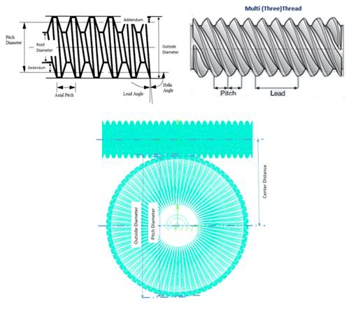
Module (Axial Plane) | Enter a value for the module expressed in the axial plane. The module is the pitch diameter divided by the number of teeth. |
Pressure Angle (Normal Plane) | Enter a nominal pressure angle in current modelling Units (default value = 20.0 deg) expressed in the normal plane. The pressure angle is the angle between the line of action and the common tangent to the pitch circles at the pitch point is the pressure angle. |
Worm and Worm Wheel | |
Name | Enter the name of the Worm and Worm Wheel. ■New ■Existing: Use the Select Gear options to load the existing gear. |
Axis of Rotation | Axis of Rotation of Worm and Worm Wheel can be one of the following: ■Orientation ■Pick (Marker) ■Global Z ■Global X ■Global Y Note: Simplified method requires an orthogonal orientation between the Worm and Worm Wheel. If the driven gear shows incorrect motion transmission, then user may try reversing the direction of 'Z' axis of worm or worm wheel by 180o. For example, try switching Z axis of worm to align with +X/-X axis of wheel and vice-versa. |
Center Location | Enter the coordinates or Pick (Markers, View location and so on.) |
No. of Teeth | Enter the number of teeth (threads) for the worm gear element and Worm Wheel. |
Face Width | Enter the axial length of the Worm and Worm Wheel. |
Bore Radius | Enter the radius for the hole in the worm and wheel (only used for graphics). |
Hand of Helix | ■LH/RH Select if the Worm thread should be Left Hand (LH) or Right Hand (RH). |
Helix Angle | Enter the helix angle for the worm wheel. Note: Adams Machinery will issue a warning if the user entered helix angle lies ±0.5o beyond the correct helix angle given by formula: tan-1 (module*(number of teeth or number of start on WORM) / WORM reference diameter)). |
Reference Diameter | Specify the reference diameter for the Worm element. |
Flank Form | Specify which flank type should be used to generate the Worm element. Available types are: ■ZA: Manufactured on turning machine with tool (straight flanks), mounted in axial section ■ZN: Manufactured on turning machine with tool (straight flanks), mounted in normal section ■ZI: Manufactured with hobbing cutter (worm flank is involute) |
Geometry Settings | ■Number of Profile Points Defines the number of points for the half tooth profile (the other half is mirrored). Default value is 10 points. The total number of points in the axial direction to create one thread will be: Thread Points = 2 * Number of Profile Points + 2 ■Circumference Point Multiplier (Worm Element only) Specifies the number of points around the circumference of the worm element, by using the following equation: (Thread Points - see above) Circumference Points = Circumference Point Multiplier * Thread Points * Teeth Number. ■Number of Helix Layers (Worm Wheel only) Defines the number of "layers" of the helical gear width should be divided into. This number should increase with increasing helix angle and gear width. For helix angle equal to 0 degrees (spur gear) this value will be automatically set to 2, otherwise the value specified in this field is used. Note: Increasing this value may improve resolution of geometry especially for wider gears but at the expense of increased time to create gear pair. |
If 3D Contact method is selected, the following options will be displayed: | |
Module (Axial Plane) | Enter a value for the module expressed in the axial plane. |
Pressure Angle (Normal Plane) | Enter a nominal pressure angle in current modelling Units (default value = 20.0 deg) expressed in the normal plane. |
Worm and Worm Wheel | |
Name | Enter the name of the Worm and Worm Wheel. ■New ■Existing: Use the Select Gear options to load the existing gear. |
Axis of Rotation | Axis of Rotation of Worm and Worm Wheel can be one of the following: ■Orientation ■Pick (Marker) ■Global Z ■Global X ■Global Y |
Center Location | Enter the coordinates or Pick (Markers, View location and so on.) |
No. of Teeth | Enter the number of teeth (threads) for the worm gear element and worm wheel. |
Face Width | Enter the face width for worm and wheel (only used for graphics). |
Bore Radius | Enter the radius for the hole in the worm and wheel (only used for graphics). |
Hand of Helix | ■LH/RH Select if the Worm thread should be Left Hand (LH) or Right Hand (RH). |
Helix Angle | Enter the helix angle for the worm wheel. Note: Adams Machinery will issue a warning if the user entered helix angle lies ±0.5o beyond the correct helix angle given by formula: tan-1 (module*(number of teeth or number of start on WORM) / WORM reference diameter)). |
Reference Diameter | Specify the reference diameter for the Worm element. |
Flank Form | Specify which flank type should be used to generate the Worm element. Available types are: ■ZA ■ZI ■ZN |
Profile | Select how the involute profile should be described using the Standard Involute Profile parameters (Profile Shifting, Addendum Factor & Dedendum Factor) or if the parameters for the Modified Involute Profile (Tip Radius, Root Radius & Tooth Thickness) should be used. ■Standard ■Modified |
If Standard profile is selected, the following options will be displayed: | |
Profile Shift Coeff. | Enter a value for profile shift coefficient for the worm gear (positive or negative value). Default value = 0.0. If this field is left blank, no profile shifting will be used. |
Addendum Factor | Enter a value for the Addendum Factor (default value = 1.0). The Addendum Factor is used to calculate the Addendum: Addendum (Normal) = Module (Normal) * Addendum Factor |
Dedendum Factor | Enter a value for the Dedendum Factor (default value = 1.2). The Dedendum Factor is used to calculate the Dedendum: Dedendum (Normal) = Module (Normal) * Dedendum Factor |
If Modified profile is selected, the following options will be displayed for the Worm element: | |
Tip Diameter | Enter a value for the tip diameter. |
Root Diameter | Enter a value for the root diameter. |
Normal Tooth Thickness | Enter a value for the tooth thickness at the reference circle in the normal plane. |
If Modified profile is selected, the following options will be displayed for the Worm Wheel element: | |
Tooth Thickness | Enter a value for the tooth thickness at the pitch circle. |
Tip Radius | Enter a value for the tip radius. |
Foot Radius | Enter a value for the foot radius. |
Tooth Modification Parameters Note: This feature is available only for Worm Wheel and only when modified individually. | |
Tip Relief Start | Tip relief is a modification of a tooth profile whereby a small amount of material is removed near the tip of the gear tooth. 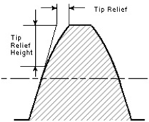 The Tip Relief Start parameter defines the position on the tooth at which the Tip Relief will start. The resulting starting radius on the gear will be: Start Radius = Tip Radius - Tip Relief Start * Module (Transverse) The Module (Transverse), MT is defined as below: MT = MN / cos(ß) If the gear is defined by Standard Involute Profile, the Tip Radius is defined as below: Tip Radius = 0.5 * MT * Z + MT * (Addendum Factor + Profile Shift Coefficient) Note: Default value is 0.0. The limit is 0.0 -1.0. |
Tip Relief Coefficient | This coefficient defines the maximum Tip Relief reached at the Tip Radius of the gear. The Tip Relief is defined by: Tip Relief = Tip Relief Coefficient * MT The tip relief will have zero value at the Tip Relief Start point and increase linearly out to the Tip Radius. Note: Default value is 0.0. The limit is 0.0 -1.0. |
Crown Magnitude | Crowning is the removal of a slight amount of tooth from the center on out to reach edge, making the tooth surface slightly convex. This method allows the gear to maintain contact in the central region of the tooth and permits avoidance of edge contact with consequent lower load capacity. Crowning also allows a greater tolerance in the misalignment of gears in their assembly, maintaining central contact. 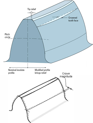 The crown magnitude is reached at the edges of the tooth and crowning is zero at the center of the tooth. The crowning is described as an arc. The Crown Magnitude is entered in length units. Note: Crowning magnitude is dependent on width of gear and is a non-negative value. |
Geometry Settings | ■Number of Profile Points Defines the number of points for the half tooth profile (the other half is mirrored). Default value is 10 points. The total number of points in the axial direction to create one thread will be: Thread Points = 2 * Number of Profile Points + 2 ■Circumference Point Multiplier (Worm Element only) Specifies the number of points around the circumference of the worm element, by using the following equation: (Thread Points - see above) Circumference Points = Circumference Point Multiplier * Thread Points * Teeth Number. ■Number of Helix Layers (Worm Wheel only) Defines the number of "layers" of the helical gear width should be divided into. This number should increase with increasing helix angle and gear width. For helix angle equal to 0 degrees (spur gear) this value will be automatically set to 2, otherwise the value specified in this field is used. Note: Increasing this value may improve resolution of geometry especially for wider gears but at the expense of increased time to create gear pair. |