Start Using Machinery Gear
With the Machinery Gear, you always create gear pairs, not single gears. The location and orientation depends on the type of gear pair to be created, see figures below.
Shaft Distance
The shaft distance must match the gear data for each gear pair created. The nominal shaft distance for spur/helical gears is equal to:
(1)(# of teeth Gear 1 + # of teeth Gear 2) / 2 * module / cos(Helix Angle)
However, the actual shaft distance should be greater than the nominal shaft distance to include gear lash and for the gears to function properly.
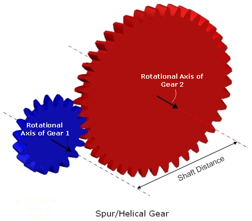
Figure 1 Spur/Helical Gear
Straight/Spiral Bevel Gear pair:
The user does not explicitly define any position of the gears since a reference position is calculated and used. The outer cone distance for Gear 1 shown in figure below is:
(2)(# of teeth Gear 1 * Module / cos(Spiral Angle) / 2 / sin (δ)
Where δ is the reference cone angle which is determined by the gear ratio.
Gear lash can be achieved by modifying the addendum modification factor of the involute gear. This factor can be expressed directly or calculated by specifying the backlash value.
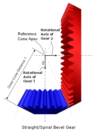
Figure 2 Straight/Spiral Bevel Gear
When all necessary data have been given in the Machinery Gear interface, gear geometry will be added to the gear parts and a contact force acting between the two gear parts. The type of contact force is dependent on method of creation; For example Simplified Gears, Detailed Spur Gears and Contact based Gears.
Hypoid Gear Pair
The reference markers for the pinion and wheel gears have to be located at the crossing point on each axis, see figure below. Their z-axes have to be oriented along their axis of rotation and point to the gears which to be created. The pinion gear reference marker has to be located and oriented as below:
■located along the y-axis of wheel gear reference marker.
■z-axis has to be normal to the y-z plane of wheel gear reference marker.
Further, the distance between the pinion and wheel gear reference markers has to correspond to the hypoid offset (a) value for the pinion and wheel gear assembly.
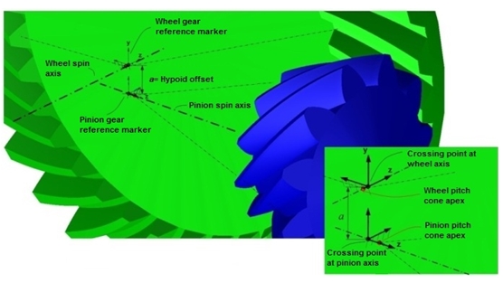
Figure 3 Hypoid Gear Pair
When all necessary data have been given in the interface, gear geometry will be added to the gear parts and a contact force acting between the two gear parts. The type of contact force is dependent on method of creation; for example, Simplified Gears or 3D-Contact based Gears.
Dual Pressure Angle
The pressure angle of each flank on both the wheel and pinion can be specified independently. There are four pressure angle inputs in total (two each on the pinion and wheel). Note that, because of one gear has a dual pressure angle that does not necessarily mean that the other must also have a dual pressure angle.
Hypoid gear flanks convention for concave and convex flanks are descriped in the below figure.
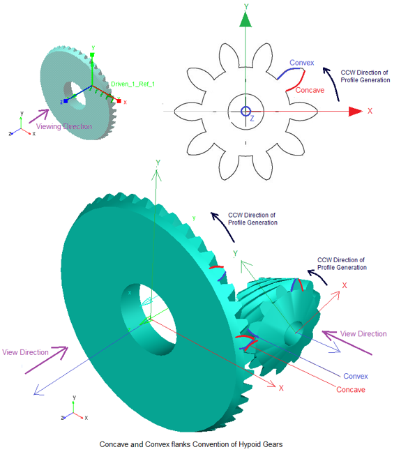
Figure 4 Concave and Convex flanks Convention of Hypoid Gears
1. Simplified method
This will be based on sense of rotation CW or CCW and respective concave or convex flanks contacts each other in a gear pair. The output request takes active flank in to the consideration.
If the active flank is concave, then concave pressure angle is considered for force calculation and vice versa for convex flanks.
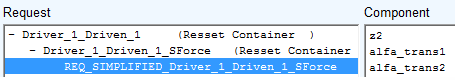
The active transverse pressure angles concave or convex based on sense of rotation are shown in request as below:
alfa_trans1 and alfa_trans2 will change in output request (if concave and concave/convex pressure angles are different on both gears)
Where:
alfa_trans1 = Pressure_angle_trans (gear1) = tan-1 (tan(pressure angle gear1)/cos(mean_spiral_angle))
alfa_trans2 = Pressure_angle_trans (gear2) = tan-1 (tan(pressure angle gear2)/cos(mean_spiral_angle))
2. 3D Contact method
No pressure angle calculation is needed for force calculation. It is based on geometry and physical contact.
Hint: | ■If the individual geometry change of one gear requires a change in another gear (for example, change in number of teeth or hand of helix) the mating gear must be modified individually. ■If you change hand of helix individual gear, then the mating gear must be modified individually. |
Cone and tooth height parameters
The below figure describe the geometry parameters related to the tooth height, face width, the different cones (pitch, face and root) and the pitch cone apex distance relative to the crossing point. Note that all cone apexes are located at the same point - at the pitch cone apex. Hence, the face and root angles can be calculated from pitch cone angle, mean cone distance, mean addendum and mean dedendum values.
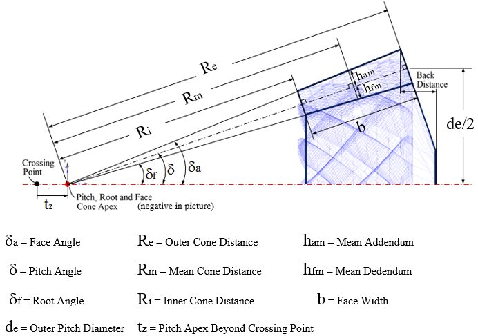
Figure 5 Cone and tooth height parameters
Spiral Angle
An (ideal) logarithmic tooth shape function is used which gives constant spiral angle throughout the lengthwise tooth direction (see below figure), that is, the inner, mean and outer spiral angle values are the same. Hence, the user specifies only one value - the mean spiral angle.
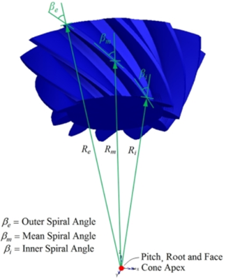
Figure 6 Spiral Angle
Tooth section profile
An involute tooth profile function is used where the user specifies a mean normal pressure angle (an) at the pitch radius, which is used both on drive and coast flank side.The mean transverse pressure angle (at) is shown below:
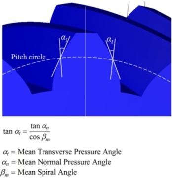
Figure 7 Tooth Section Profile
Hand of spiral angle and hypoid offset
The sign of the hypoid offset and the hand of the spiral angle of the gears have to match each other in order to properly assemble the pair. When viewing a hypoid gear pair in such way that the pinion gear is located at the right and the wheel gear cone is pointing out from picture, the following applies:
■If the pinion axis is located below the wheel axis as in the left case (the hypoid offset is a positive value), the wheel gear spiral angle has to be right hand sided while the pinion gear has to be left hand sided.
■If the pinion axis is located above the wheel axis as in the right case (the hypoid offset is a negative value), the wheel gear spiral angle has to be left hand sided while the pinion gear has to be right hand sided.
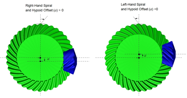
Figure 8 Hand of spiral angle and hypoid offset
Geometry Settings
The Machinery Gear creates external and internal spur and helical gear shell geometry. A hole for shaft can be included for the external gear geometry (optional), while for the internal gear geometry it is possible to enter an outer radius of the gear.
The created geometry is a closed solid geometry, which makes it possible for Adams View to automatically calculate the correct mass and inertia for the gear, with any given material or density.
It is possible to define the level of detail for the gear geometry (solids). With a more detailed geometry, a better, smoother, result will be achieved (this is not valid for the Simplified Gears).
To set level of detail, open the Geometry Settings dialog box. The following two parameters will control the level of detail for the gears:
■Number of Profile Points: Defines the number of points for the half tooth profile (the other half is mirrored) through which a curve is fit.
Note: | Increasing this value may improve resolution of geometry especially for larger gear teeth but at the expense of increased time to create gear pair. |
■Number of Helix Layers: Defines the number of "layers" of the helical gear width should be divided into. This number should increase with increasing helix angle and gear width. For helix angle equal to 0 degrees (spur gear) this value will be automatically set to 2, otherwise the value specified in this field is used.
Note: | Increasing this value may improve resolution of geometry especially for wider gears but at the expense of increased time to create gear pair. |
Deleting Gears
Deletion
RMB on gear-pair in model browser and select Delete. If gear element is shared between two gear-pairs, it will not be deleted. Only gear-force will be deleted. Independent gear pair will be deleted completely.
Modify
RMB on gear-pair in model browser and select Modify. This will open up the wizard for modification.
Activating - Deactivating Gears
Gear pair refers to a force (SFORCE or contact) which transmits motion from one gear element to the other. Gear pair ties two gear elements by SFORCE or contact force. Two individual gear elements associated with a gear-pair have their own joint on which motion/torque can be applied.
When user deactivates gear pair, the force (SFORCE or contact) is disabled, making two gear element independent from gear pair. These two gear elements can simulate independently.
When user deactivates gear element, the gear element and its dependent entities (motion or torque) are deactivated.
Planetary Gear Set
Planetary gear set is gear assembly that consists of 3 primary components. A ring Gear (The outer most gear), 3 (or more) planetary gears that are housed by a Planetary carrier assembly (the middle gears), and a Sun Gear (The gear in the center of the gear set).
Planetary gear has simplified and 3D contact methods. This methods calculates the gear forces and backlash between the gear pair. It is useful when function is neglected. It uses ADAMS GFORCE to calculate the force. Gear pair has to be constrained to the same plane. For more information, see Create Planetary Gear dialog box.