Standard Interface - Use Signal Manager and run interactive analyses
Overview
This tutorial guides you through the process of how to connect control systems, run full vehicle simulations with different setup of the control systems, and review the results in the Standard Interface mode. The process of adding disturbance signal is also covered here.
It is assumed that you have already started Adams Car and loaded the Adams Mechatronics plugin.
The main steps in the tutorial are listed as:
■Open assembly which includes ABS and ESP control systems
■Connect control systems with Signal Manager
■Run analyses with ESP turned on and off
■Review the result differences
■Add disturbance and rerun the analysis
■Study disturbance results
■Study delay result
Open assembly which includes ABS and ESP control systems
Open the demo assembly model MDI_Demo_Vehicle_lt_ABS_ESP_00.asy located in the Adams Mechatronics shared database:
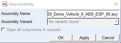
The assembly originates from a standard Adams Car demo model with two additional subsystems added, the ABS and the ESP (Electronic Stability Program) control subsystems. The control systems are not yet connected to each other or to the mechanical model.
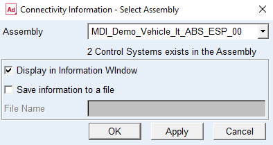
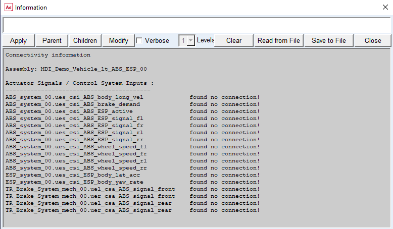
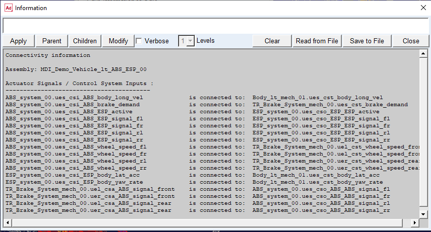
Examine and verify the connectivity status of the control systems in the assembly by choosing Mechatronics → Info → Connectivity. The Info Connectivity dialog box below shows the number of existing control systems in the assembly.
Connect control systems with Signal Manager
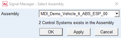
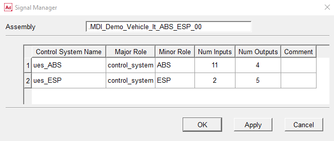
The next step is to define how the control systems are connected to the transducer and actuator signals of the mechanical system. To do this, go to the Signal Manager using Mechatronics → Signal Manager. First the Signal Manger – Select Assembly will show up to let you select from the active assemblies. In addition, here you can see how many control system exist in each assembly as a text under the Assembly field. By selecting OK or Apply the Signal Manager dialog box will be displayed.
Here you can review all existing control systems in the selected assembly and then select one by double-clicking on control system name or any cell in the row. Let’s start with the ABS control system by double-clicking on ues_ABS cell or any other cell in the same row.
Now the Signal Manager loads the selected control system information such as the (control) System Name, its corresponding Major Role, Minor Role, and Comment. Furthermore, it lists all existing ports in two separate Inputs and Outputs tables.
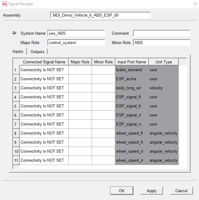
Note that:
■Each table is divided into white and gray areas; the gray areas are related to port information (name and unit type) of the control system and the white areas are related to connectivity information (connected signal name, major, and minor role), that is, information of connected signals to the ports
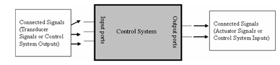
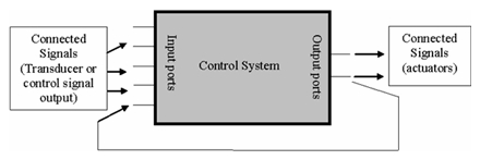
■In Inputs table, the columns related to Connected Signal (white area) are in the left side of the table whereas in Outputs table, they are in the right side of the table. This is basically to resemble the following model. Input and output signals are normally connected to the control system from left and right side, respectively.
The next step is to connect the proper signals to the ports in which the Connected Signal Name column shows ‘Connectivity Is NOT SET’. By clicking on the each cell related to connectivity information (white area), a new windows pops up where you select and connect the appropriate (transducer or control system output) signal to the selected input port name.
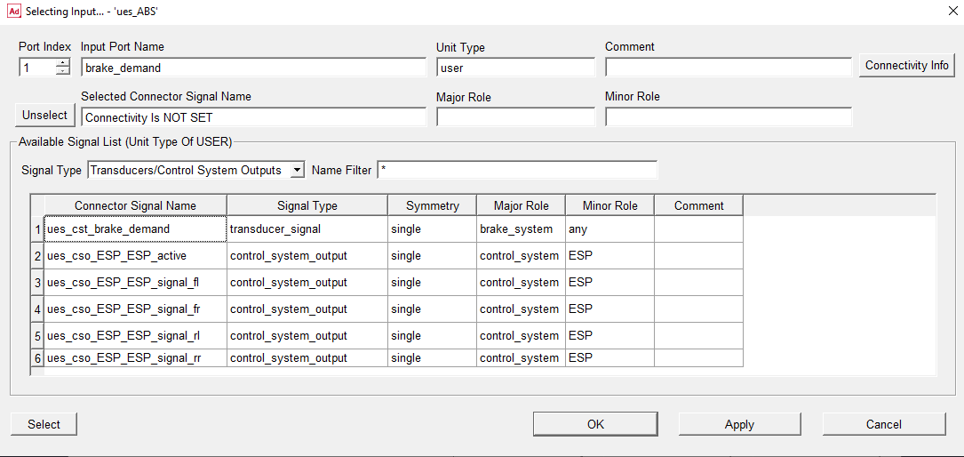
Getting familiar with Selecting Input… dialog box
■On the top of Selecting Input dialog (first row), information related to selected input port index, port name, unit type, and comment is displayed.
■By changing the port index (leftmost field in the first row) you can display the other input ports and edit the connectivity information.
■Clicking on Connectivity info button (rightmost in the first row) you can see whether any signal is already connected to the port. The usage of this button is concerned with cases where a port might be connected to a signal from a previous model.
■The second row shows which signals are already connected (or selected to be connected) to the input port, and its major and minor roles.
■Clicking the Unselect button (leftmost in the either row) unselects the selected connector signal, however, this will not take effect until the OK or Apply button is clicked.
■Available Signal List (lowermost field and table) displays all selectable signals in a table, that is, (transducers or control system outputs) signals which have the same unit type as the input port. Let’s explain this by an example; in the current case, because the brake_demand signal has user unit type, all signals (either transducers or control system outputs) which have a unit type of user are listed in the table.
■The available signal list can be filtered by Signal Type (curtain menu) and Name Filter field. This is to help you to find the appropriate signal more conveniently.
■You can select a signal (to be connected to a selected port) from the table by selecting one of the signal’s cell and then clicking the Select button (lower leftmost). However, this will not take effect until either the OK or Apply button is clicked.
■Double-clicking on a signal in the table is implemented as a short cut for
♦select a signal
♦apply the selection
♦show the next port
This is to speed up the process of connecting signals to the ports one after another.
■When a signal from the table is already selected, it appears with blue background color in the table.
■Similar to other dialog boxes in Adams, the OK button closes the Selecting Input dialog box and returns to the previous window while the Apply button applies the changes and keeps the current dialog box open.
Now try to get the feeling of the Selecting Input dialog box by connecting the input signals as shown in the following picture. As explained earlier, a quick way to select signals is to double-click on them (see preceding explanation). After connecting all input signals, return to Signal Manager by clicking OK or Cancel.
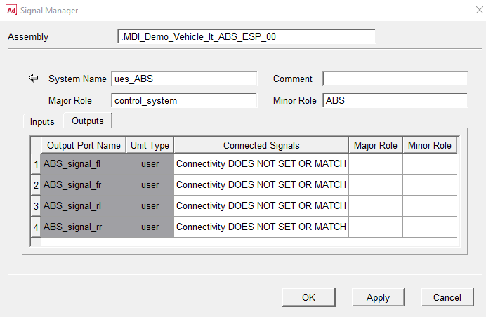
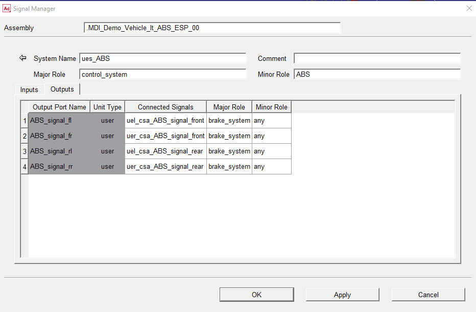
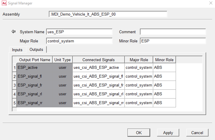
Now we want to connect the Outputs signals. Therefore you go to Outputs table by selecting its tab as shown in following illustration.
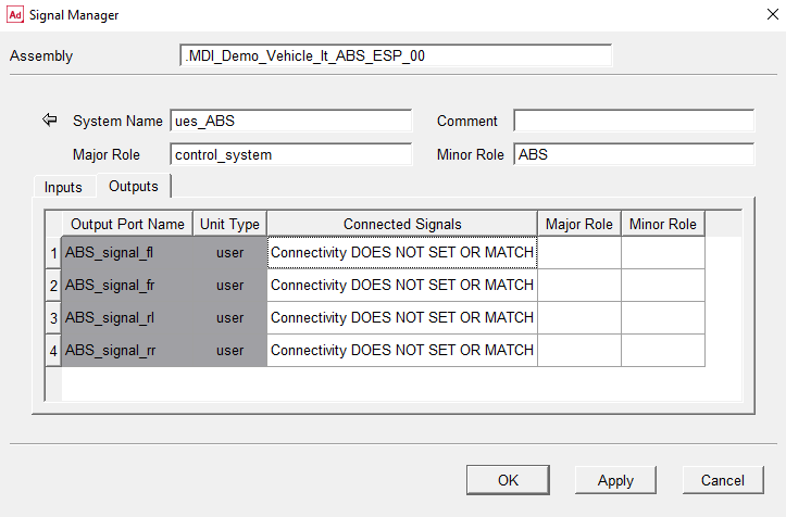
Similar to the Inputs table, the port information (name and unit type) columns are distinguished by gray background, however, in contrary to the Inputs side, they are located in the left side of the table to resemble the following model illustration.
As can be read from the Outputs table, the “connectivity DOES NOT SET OR MATCH” for the output ports at the moment. Therefore we try to connect the output ports by using Selecting Output … dialog box via double-clicking on Connected Signals column or any cell on the same row (white area). This will display the Selecting Output … dialog box.
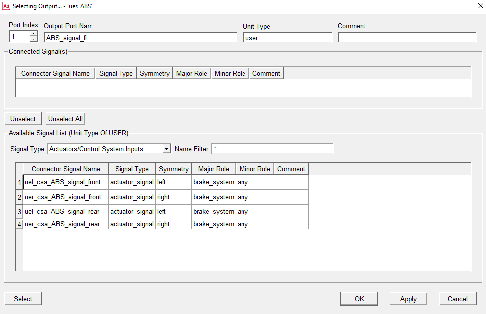
Getting familiar with Selecting Output… dialog box
The Selecting Output dialog box is very similar to Selecting Input dialog box except from that here the connected signal(s) are displayed in a table instead of a single row. The reason is that an output port can principally be connected to more than one actuator signal or control signal input. Knowing this, the other features are as follows.
■Connected Signal(s) table lists signals which are currently connected (or selected to be connected) to the output port, and their signal type, symmetry, major role, minor role, and comment.
■Use Unselect button (lower the connected signal(s) table) to unselect one or several connected signals from the table. However, keep in mind that this will not take effect until either the OK or Apply button is clicked.
■Use Unselect All buttons (lower the connected signal(s) table) to unselect all connected signals in the table. However, again note that this will not be applied until either the OK or Apply button is clicked.
■The Available Signal List is similar to the Input side, however, in the output port side, only actuators and control system inputs of the appropriate unit type are listed. As an example, in current case, all signals (either actuators or control system inputs) that have a unit type of user are listed in the table because the signal ABS_Signal_fl has user unit type.
■You can select one or more signals (to be connected to a selected port) from the table by selecting on one of the signal’s cells and then clicking the Select button (leftmost lower). Use the Ctrl button on your computer keyboard to choose more than one signal. By pressing select, the selected signal will appear in upper table, however, the selection will not take effect until either the OK or Apply button is clicked.
■If one or several signals are selected by clicking the Select button, their cells’ background color changes from white to blue in the Available Signal List table and consequently they will also appear in the Connector Signal(s) table.
■If a signal (actuator or control signal input) appears with gray background color in the Available Signal List table, it means that the signal has been already connected to an output port and therefore can not be selected.
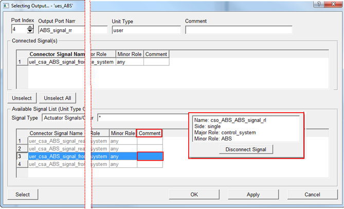
■Right-clicking on the comment column in the Available Signal List table pops up a small window where it is possible to review the connectivity information and a Disconnect Signal button for disconnecting the signal to make it available for selection.
■Double-clicking on a signal in the table is a short cut for
♦select the signal
♦apply the selection
♦show the next port
Now try to get the feeling of Selecting Output … dialog box by connecting the input signals as shown in the following figure. As explained earlier, a quick way to select signals is to double-click on them (see preceding explanation). After connecting all input signals, return to Signal Manager by selecting OK or Cancel.
By now you have completed the setup of the ABS control system connections. Now we go back to select and setup the EPS control system by clicking the Arrow Icon  on the top-left of the Signal Manager.
on the top-left of the Signal Manager.Proceed then by repeating the preceding steps for the ESP control system by selecting (double-clicking) the ESP control system:
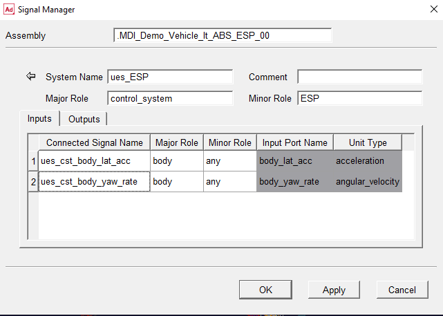
Note that the ESP control system outputs already have the proper connections to the ABS control system. In fact, they have been set in the previous steps (input side of ABS control system).
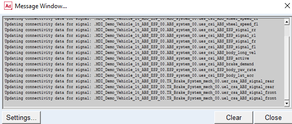
Press OK in the Signal Manager dialog box and following text will appear in the message window:
Now use the info connectivity feature for verifying that all control system inputs and actuator signals in the assembly are properly connected:
Save the assembly and the subsystems using menu File → Save. Note due to the connections that were defined by using the Signal Manager following subsystems have been modified:
■ABS_system_00.sub
■ESP_system_00.sub
■TR_Brake_System_mech_00.sub
All these subsystem files have now been updated with the appropriate connectivity data. This means that next time you open the assembly, all connections are already made.
Run the analyses with ESP turned on and off
Now we will submit a single lane change manoeuvre to see how the ESP influences the handling behavior of the vehicle. The ESP control system is activated by default.
Before executing the full vehicle analysis and to compare the results later on, we need to activate two requests from the ESP control system outputs. Start to modify the ESP control system output ESP_signal_fl by using Mechatronics → Control System → Output. This displays the following dialog box:
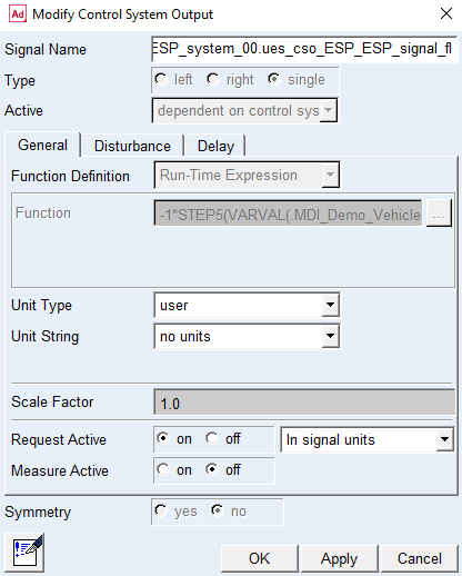
Repeat the same step for the ESP control system output ESP_signal_fr
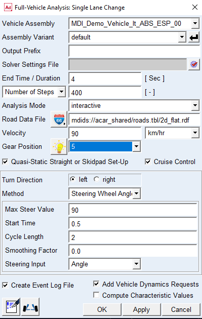
Now submit the single lane change analysis (Simulate → Full-Vehicle Analysis → Open-Loop Steering Events → Single Lane Change) with the following settings:
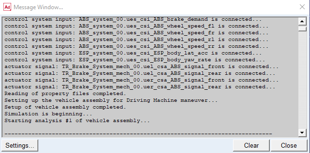
During the read property file procedure the control system inputs and actuator signals get connected:
We are now going to deactivate the ESP controller to compare the results. Use Mechatronics → Control System → Modify to display the following dialog box:
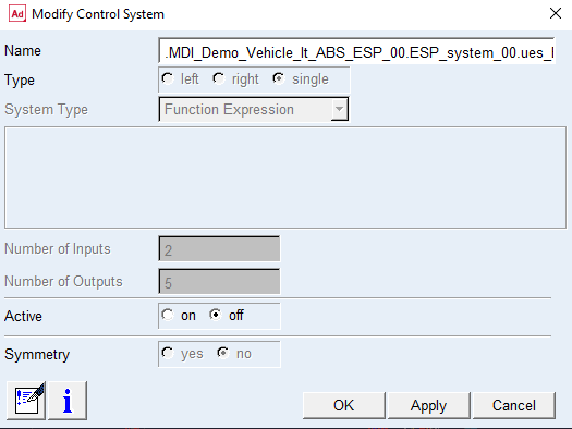
Set the activity to 'off' and select OK. The following message window appears:
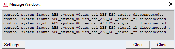
Consequently, we have now deactivated the ESP controller. Therefore, all the control system inputs of the ABS system which were dependent on the output from the ESP have been disconnected, meaning that they will receive zero values on those channels.
Rerun the analysis with the same settings as before.
Review the result differences
Open the post processor and select the body yaw rate signal as shown in the following picture:
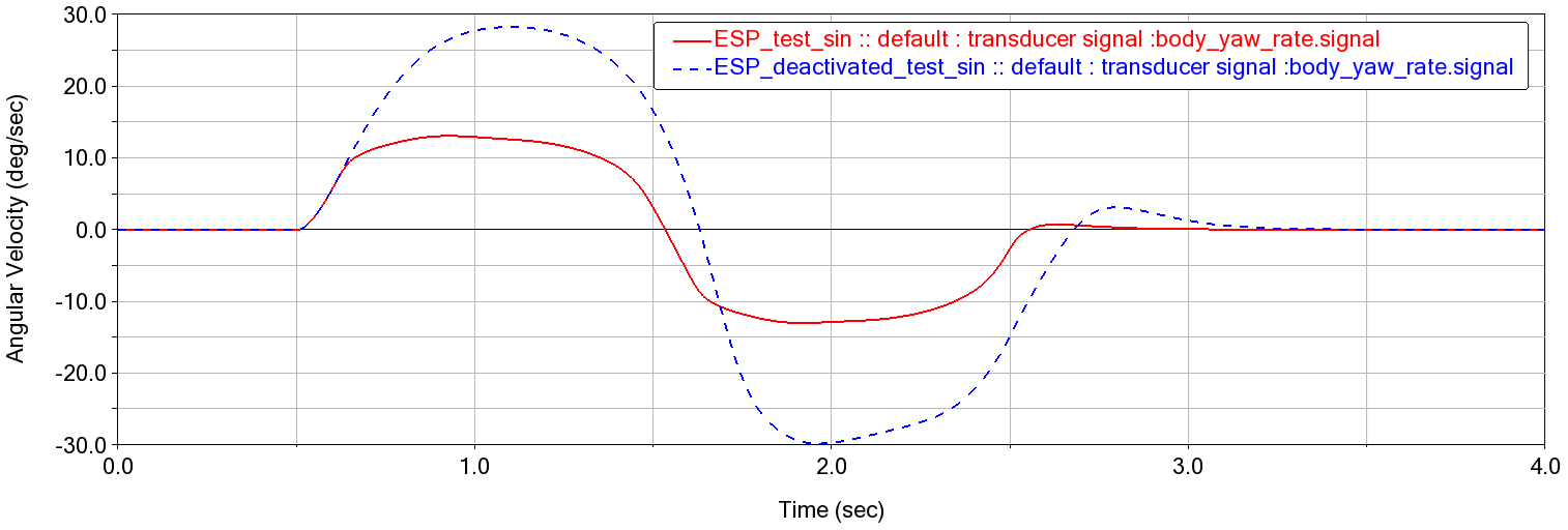
Clearly, deactivating the ESP causes the car to reach much higher yaw rates during this particular manoeuvre.
Please note that Adams Mechatronics has predefined requests for all types of control signals:
..._model_units (expressed in model units):
..._signal_units (expressed in transducer/actuator signal specific unit)
Add disturbance and rerun analysis
Now a sinusoidal disturbance signal will be added to the ESP control system input body_yaw_rate.
But before that, first activate the ESP control system again and proceed by displaying the control signal dialog box using Mechatronics → Control System → Input:
Choose to add a disturbance ASCII file (sin_amp1to5_freq2_3s.daf) from the shared database and activate all requests in the general tab container. All control system inputs and output requests are deactivated by default.
The beginning of the disturbance file looks like:
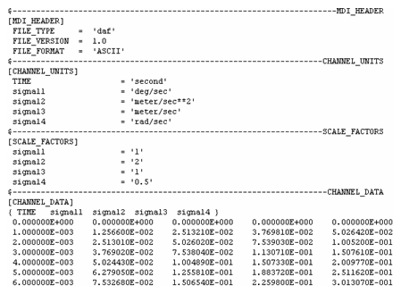
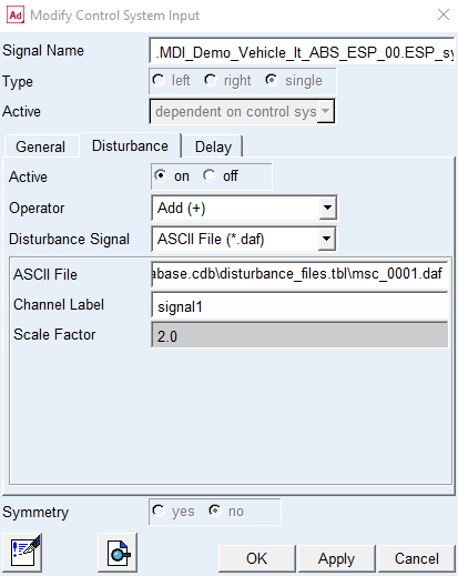
In this case the channel label signal1 is chosen and according to the channel unit block the channel unit is deg/s. With raw signal amplitude of 1 from the file and a channel scale factor set to 2 in the dialog box, we can expect a disturbance amplitude of 2 deg/s.
Now change the values for the End Time and Number Of Steps to 3 sec and 300 steps respectively and rerun the analysis.
Study disturbance results
Open the postprocessor and select the different result set components available for the ESP control system input body_yaw_rate as following figure:
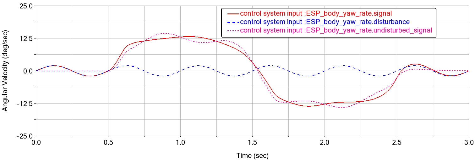
The following result set components are available for the request ues_csi_ESP_body_yaw_rate_model_units:
..._model_units.signal (signal into ESP control system):
..._model_units.disturbance (sinusoidal signal with amplitude of 2 deg/s)
..._model_units.undisturbed_signal (received from connected transducer signal)
..._model_units.function (same as undisturbed_signal in this case)
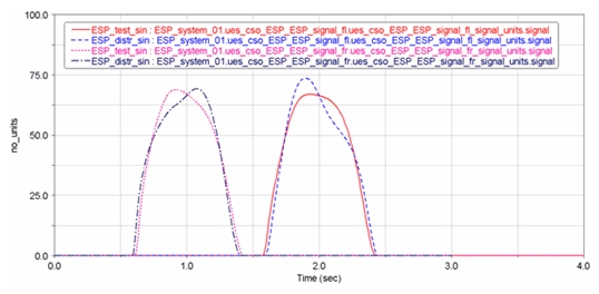
The disturbance affects the behavior of the ESP control system. Compare the new results from the ESP control system output signals ESP_signal_fl and ESP_signal_fr with those from the first run:
Add delay and rerun analysis
Now you remove the disturbance and consider adding a delay time function. Go to Modify Control System Input dialog box and activate the delay with value of 0.02 s as illustrated in picture below.
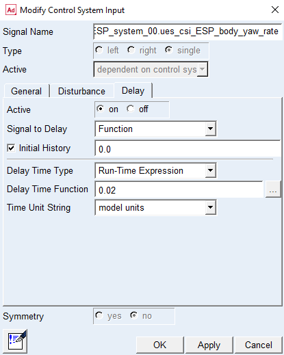
Click Apply.
In order to run the analysis, you need to choose the C++ Adams solver as the delay function is defined in this solver. You can do this from the Settings → Solver → Selection … .
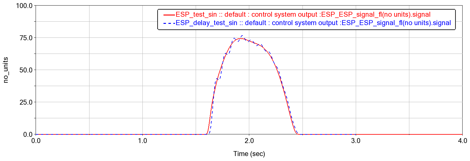
Rerun the analysis, and go to the post processor to see the delay applied in the signal.
The delay affects the behavior of the ESP control system. Compare the new results from the ESP control system output signal ESP_signal_fl with one from the first simulation.
You have now finished the tutorial.