Adams View - Setup and run Excavator model
Overview
This tutorial will guide you through the process of creating four systems in Easy5, connecting the signals in Adams Mechatronics and running a simulation for the combined system. For this tutorial a model of an excavator is used. The control systems are imported as four different external library files and consist of three different PI-controllers and a simple hydraulic system.
The main steps covered in the tutorial are:
■Open the model and perform a test simulation
■Create external system library files
■Create four control systems
■Create transducer signals
■Create actuator signals
■Apply the control system to the mechanical system
■Connect the signals in signal manager
■Simulate the model and review the results
Import the model file and simulate a test.
First, copy the tutorial directory <Adams installation>/amech/examples/aview/tutorial_excavator to your working directory. Start Adams View, select the just created directory as working directory and import the Adams command file excavator_start.cmd to load the model.
This is a model of an excavator where the turret, boom, arm, and bucket are controlled by four different motion statements. In this tutorial the motions for moving the hydraulic cylinders for the boom, arm and bucket will be replaced by a hydraulic system controlled by three different controllers.
First examine how the excavator moves using motions by performing a scripted simulation using the motions. A simulation script named simple_run is prepared. This simulates 25 seconds with 1250 output steps and starts with an initial equilibrium simulation.
Simulate → Scripted Controls
Animate the results to see how the excavators move. The motion of the hydraulic cylinders will be used as the desired values sent to the controllers that will regulate the hydraulic system to deliver correct forces.
Go to the Postprocessor tool by pressing F8, switch the Source to Result Sets, and plot the desired boom displacement boom_ACT_set_value and then overlay the actual boom hydraulic cylinder position boom_l_ACT_EZ5_position. Note that they follow each other since the system is controlled by a motion statement. After reviewing the results, leave your Adams session open so that you can work on the model later. Otherwise, you will need to reload the model after finishing the next section.
Create External System Library files
In this tutorial we will start with creating the four control systems, but we could as well have started by creating the transducer and actuator signals. But before we use the control systems in Adams we need to build the Easy5 External System Libraries (ESL’s) and we also need to create property files in Adams Mechatronics to be able to import the external control systems. Start by opening MSC Easy5 and open the model arm_controller found in <adams_installation>\amech\ examples\aview\ tutorial_excavator\easy5 folder. In Easy5 you now have a model of a PI controller and an Adams block as illustrated below.
Please note that in all control systems in this tutorial the Adams block is already defined and exists to save time. In a real application, the Adams block should be manually created or defined. This procedure has been covered in standard Adams Control manual in detail or tutorial for ball and beam example of Adams Mechatronics. The procedure can be summarized as follows:
1. define the (number/name of inputs/outputs of) control system in Adams Mechatronics
2. perform a Plant Export in Adams Mechatronics
3. create an Adams block in the control system package from the exported plant, and
4. connect the control system and Adams block as depicted in the above picture.
The above controller, similar to all other controllers in this tutorial, is a simple PI-controller that takes a desired signal and a feedback signal as input and delivers a current output that will control the servo valve in the hydraulic system.
We need to export this model to get our external system library from Easy5. In Easy5, from the top menu select
Build menu → Export Model As → Adams External System Library… .
The following dialog box is displayed
Make sure that in General tab the value for Use Design Parameters is set to Yes (this enables the previously selected Easy5 parameters in arm_controller.0.ezadb to be used as design parameters in Adams) and then select Export and then close the dialog box. Upon a successful model export, a library file is generated called arm_controller.dll (.so, .sl) located in the Easy5 working directory.
Now redo the same steps for the boom_controller, bucket_controller and the hydraulic_system model to build all necessary External System Libraries). After exporting the ESL's from Easy5, you may close Easy5.
Create External System Library Property Files
We now need to create External System Library property files to be able to use these libraries in Adams Mechatronics in a effective way. In Adams View, using the excavator model from the previous section, create the External System Library property files:
Mechatronics → Tools → ESL Property File… .
(Note that these Mechatronics menus are loaded by the Mechatronics Plugin. In this case, the plugin was automatically loaded by this Adams model, but this can be loaded manually by selecting Tools → Plugin Manager → Mechatronics → Load)
The following dialog box displays where you need to fill in the external system library file name, the ESL property file name, and make sure the Target Directory is your working directory.
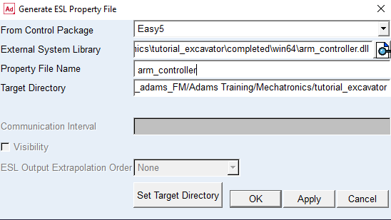
Select OK or Apply to create the ESL property file. You should see a message similar to the following in Adams:
Copying 'file://C:/examples/aview/tutorial_excavator/easy5/arm_controller.dll' to 'file://C:/ /examples/aview/tutorial_excavator/win32/arm_controller.dll'.
Copying 'file://C:/examples/aview/tutorial_excavator/easy5/arm_controller.xfe.ezanl' to 'file://C:/examples/aview/tutorial_excavator/win32/arm_controller.xfe.ezanl'.
Copying 'file://C:/examples/aview/tutorial_excavator/easy5/arm_controller.dll.manifest' to 'file://C:/examples/aview/tutorial_excavator/win32/arm_controller.dll.manifest'.
Library property file 'file://C:/examples/aview/tutorial_excavator/arm_controller.esl' is created successfully.
Now, create ESL property files also for the other External System Library files i,e., boom_controller, bucket_controller, and hydraulic_system. Use the same name for the ESL property file name as the ESL file name.
Create Control Systems
Next we will create the four control systems in Adams Mechatronics of external system library type. From the top menu select
Mechatronics → Control System → New…
to show the Create Control System dialog box. You select the control system and type, the external Library Property File (.esl), and number of inputs and outputs as shown in the figures below.
Before selecting OK or Apply, select  icon on the lower left corner to start the Control Signal Editor, where the input/output ports, unit types, unit strings, and so on are defined. Click on the first cell below the Signal Name column and start to fill the table as following picture depicts. It is required that the signals are defined in the same order as the External System Library.
icon on the lower left corner to start the Control Signal Editor, where the input/output ports, unit types, unit strings, and so on are defined. Click on the first cell below the Signal Name column and start to fill the table as following picture depicts. It is required that the signals are defined in the same order as the External System Library. By defining the correct units that the external control system expects, Adams Mechatronics automatically converts the signals to correct units.
The output signal is created in the same way, but in this case we set the unit type to user since current is not defined in Adams Mechatronics. This output signal will later be connected to an input in the hydraulic system that expects a current signal.
Then select OK in Control Signal Editor, followed by OK in the Create Control System. A message window verifies that the control system inputs/output have been created as shown below.
Two more control systems for the other two controllers also needs to be created in the same way as above, with the following specifications.
Control system name: boom_controller
Library property file: boom_controller.esl
Inputs:
# | Name | Unit type | Unit string | Scale |
|---|---|---|---|---|
1 | boom_demand | length | Model units | 1.0 |
2 | boom_position | length | Model units | 1.0 |
Outputs:
# | Name | Unit type | Unit string | Scale |
|---|---|---|---|---|
1 | boom_cur_sig | user | no_units | 1.0 |
Control system name: bucket_controller
Library property file: bucket_controller.esl
Inputs:
# | Name | Unit type | Unit string | Scale |
|---|---|---|---|---|
1 | bucket_demand | length | Model units | 1.0 |
2 | bucket_position | length | Model units | 1.0 |
Outputs::
# | Name | Unit type | Unit string | Scale |
|---|---|---|---|---|
1 | bucket_cur_sig | user | no_units | 1.0 |
Now we will create the control system for the hydraulic system in the same way, but with 11 inputs and 4 outputs. The hydraulic system needs a current input for each hydraulic cylinder to regulate the servo valve which controls the hydraulic cylinder. Hydraulic cylinder position and velocity are also sent as feedback to the hydraulic control system. Output from the hydraulic system is four cylinder forces. This totally yields 11 inputs and 4 outputs. Now create the hydraulic control system as shown in the following figures.
The inputs should be defined as the following figure shows.
And the output should be defined as the following figure shows.
Then select OK in Control Signal Editor, followed by OK in the Create Control System. A message window verifies that the control system inputs/output have been created.
By now we have created all the control systems needed for the model. Next we will move on to create the transducer signals that will feed the control systems with appropriate information.
Create Transducer Signals
To feed the control systems with input signals from the mechanical model, virtual transducer signals are created. We need to create transducer signals that measure the hydraulic cylinder positions and velocities.
We start with one of the arm transducers. Go to
Mechatronics → Mechanical System → Transducer Signal → New
to create the first transducer according to picture below. Note that you have the possibility to set request and measure activity on or off.
to create the first transducer according to picture below. Note that you have the possibility to set request and measure activity on or off.
You may use Mechatronics → Info → Signals… to verify that the rest of the transducers are already prepared according to the table below..
Name | Function | Unit type | Unit string |
|---|---|---|---|
arm_velocity | VZ(MARKER_65,MARKER_66,MARKER_66) | velocity | Model units |
arm_set_value | VARVAL(arm_ACT_set_value) | length | Model units |
Boom_l_position | DZ(MARKER_63,MARKER_64,MARKER_64) | length | Model units |
Boom_l_velocity | VZ(MARKER_63,MARKER_64,MARKER_64) | velocity | Model units |
Boom_r_position | DZ(MARKER_61,MARKER_62,MARKER_62) | length | Model units |
Boom_r_velocity | VZ(MARKER_61,MARKER_62,MARKER_62) | velocity | Model units |
Boom_set_value | VARVAL(boom_ACT_set_value) | length | Model units |
Bucket_position | DZ(MARKER_67,MARKER_68,MARKER_68) | length | Model units |
Bucket_velocity | VZ(MARKER_67,MARKER_68,MARKER_68) | velocity | Model units |
Bucket_set_value | VARVAL(bucket_ACT_set_value) | length | Model units |
You have now created all necessary transducer signals in the mechanical system. Our next step will be to create the actuator signals which control the hydraulic cylinders.
Create Actuator Signals
Actuator signals are signals that are received from the control system and should be connected to the mechanical system. In this case there are four hydraulic cylinder force signals that should be connected to the system. First we need to create the actuators and then we need to use them in the mechanical system. Display the Create Actuator Signal dialog box via the top menu
Mechatronics → Mechanical System → Actuator Signal → New
to create an actuator signal according to the figure below.
Select OK or Apply to create the actuator signal. You may use Mechatronics → Info → Signals to verify that the actuator signals for the boom and bucket are already prepared in the model.
Apply the control system to the mechanical system
Next we need to reference these actuator signals in the mechanical system. This is done by modifying the force statements that are used in hydraulic cylinders. The actuator signal is stored in a variable named signal_variable under the actuator signal object. The force function should be set to get the value of this signal. To modify the arm_ACT_actuator, you may use the top menu Edit → Modify and look for all forces using Filter. See figure below for how to modify the arm_ACT_actuator force.
Next, continue to modify the remaining forces, that is, boom_l_ACT_actuator, boom_r_ACT_actuator, bucket_ACT_actuator to reference the corresponding actuator signal variable.
Connect the signals in Signal Manager
The next step is to define how the control systems are connected to the transducer and actuator signals. To do this, go to the Signal Manager using the menu
Mechatronics → Signal Manager → Display…
First the Signal Manager – Select Model will show up to let you select from the active models (in this case only one model exists, that is, excavator_model). Additionally you can also see how many control systems exist in each model.
By selecting Apply the Signal Manager will be displayed.
In the Signal Manager you can review all existing control systems in the selected model and then select one by double clicking on the control system name. 
Let us start with the arm controller and double click on ues_arm_controller cell (or on any other cell in the same row). Now the Signal Manager loads the selected control system information and lists all existing ports in two separate Input and Output tabs.
Note that:
■Each table are separated into white and gray areas; the gray area are related to port information (name and unit type) of the control system and the white area is related to connectivity information (connected signal name), that is, information of connected signals to the ports
■In Inputs table, the columns related to Connected Signal (white area) are in the left side of the table; whereas in Outputs table they are in the right side of the table. This is basically to resemble the signal flow model illustrated in the following figure. Input and output signals are normally connected to the control system from left and right side, respectively.
By double clicking on “Connectivity Is NOT SET” cell, the Selecting Inputs dialog box will be displayed as follows.
Getting familiar with Selecting Input… dialog box
■On the top of Selecting Input dialog box (first row), information related to selected (in previous step) input port index, port name, unit type, and comment is displayed
■By changing the port index (leftmost field in the first row) you can navigate through other input ports and edit the connectivity information
■Second row shows which signal are connected (either already or selected to be connected) to the input port, and its corresponding major and minor role
■Clicking the Unselect button (leftmost in the second row) unselects the selected connector signal, however, this will not take effect until the OK or Apply are selected
■Available Signal List (above the table) displays all selectable signals in a table, that is, (transducers or control system outputs) signals which have the same unit type as the input port. Let’s explain this by an example. In current case as the arm_position signal has length unit type, all signals (either transducers or control system outputs) which have a unit type of length are listed in the table
■The available signal list can be filtered by Signal Type (‘curtain’ menu) and Name Filter field. This is to help you to find the appropriate signal more conveniently
■You can select a signal (to be connected to selected port) from the table by selecting one of the table cell in which signal attributes are shown and then clicking the Select button (lower below table). However, this will not take effect until the OK or Apply are subsequently selected
■Double-clicking on a signal in the Available Signal list table is implemented to be a short cut for
♦selecting a signal
♦applying the selection
♦showing the next port.
This is to help you in the process of connecting signals to the ports one by one.
■When a signal from the table is already selected, its row in the table have blue background color in the table
■Similar to other dialog boxes in Adams, OK closes the Selecting Input dialog box and returns to the previous windows while Apply button applies the changes and keep the current dialog box alive
Now try to get the feeling of Selecting Input dialog box by connecting ues_cst_arm_set_value to arm_demand. As explained earlier, you may just double click on ues_cst_arm_set_value which select the signal and lead you directly to the next port, that is, arm_position. Similarly, select ues_cst_arm_position to be connected to arm_position and then select OK. The arm_controller input signals should be connected as the following picture.
The outputs from the control systems will remain unassigned for now (those will get completed when dealing with hydraulic system controller). Select  icon in top left area of dialog box to continue with the input side of the boom and bucket controller in a similar way as following pictures shows.
icon in top left area of dialog box to continue with the input side of the boom and bucket controller in a similar way as following pictures shows.
Next, continue with the hydraulic system controller and connect the input signals according to the following figure.
Now we want to connect the Outputs signals. Therefore we select the Outputs tab and select the appropriate signal connections as shown in following illustration.
After connecting all input signals, return to Signal Manager by selecting OK.
Next, display the arm controller again to verify that the output is now connected to the hydraulic system. By now, you have completed the setup of assigning all transducer and actuator signals to the control systems. Select OK twice to go back to the main Adam windows. A message window pops up with messages confirming that the control system signals are connected.
Deactivate the Motions
Before performing a simulation, we need to deactivate the motion statements used in the introductory simulation. First from the top menu, select
Edit → Deselect All
to make sure that nothing is selected, then from top menu select
Edit → Deactivate
This will open the Database Navigator. In the list find and select, arm_Motion, boom_Motion, and bucket_Motion (following picture) and select OK. This will deactivate the motion statements that were used to control the motion of the excavator.
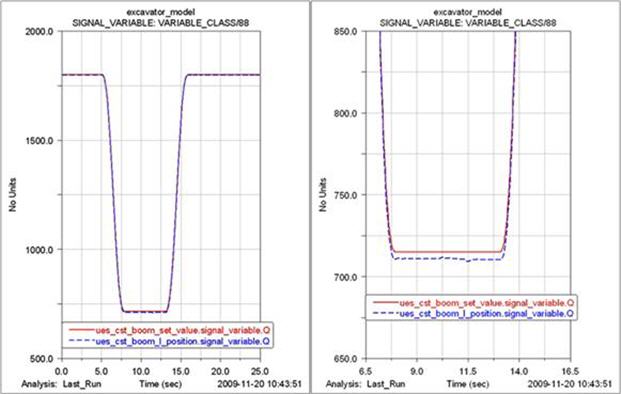
Simulate the model and review the results
Rerun the simulation script that was used in the beginning of this tutorial and animate the model again. Once again plot the signal ues_cst_boom_set_value in the Adams Postprocessor and then overlay the actual boom hydraulic cylinder position ues_cst_boom_l_position. Note the difference of using these control systems instead of the motion controlled system.
You have now finished this tutorial.