GFORCE
The GFORCE statement defines a force element that consists of three orthogonal translational force components and three orthogonal torque components. You may define the GFORCE statement through user-specified function expressions in the Adams Solver (FORTRAN) dataset or through user-written subroutines.
Format
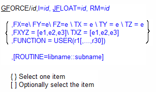
Arguments
FUNCTION=USER(r1[,...,r30) | Specifies up to thirty user-defined constants to compute the force components in a user-defined subroutine GFOSUB. |
FX=e | Specifies the magnitude and sign of the x component of the GFORCE translational force. Adams Solver (FORTRAN) applies this force parallel to the x-axis of the RM marker. |
FY=e | Specifies the magnitude and sign of the y component of the GFORCE translational force. Adams Solver (FORTRAN) applies this force parallel to the y-axis of the RM marker. |
FZ=e | Specifies the magnitude and sign of the z component of the GFORCE translational force. Adams Solver (FORTRAN) applies this force parallel to the z-axis of the RM marker. |
I=id | Specifies the marker at which Adams Solver (FORTRAN) applies the forces and torques. You must ensure that the I marker is a fixed marker and on a different part than the JFLOAT marker. Because I is a fixed marker, Adams Solver (FORTRAN) always applies the force at a fixed point on the part containing the I marker. |
JFLOAT=id | Specifies the marker at which Adams Solver (FORTRAN) applies the reaction forces and torques. You must ensure that the JFLOAT marker is a floating marker and on a different part than the I marker. Adams Solver (FORTRAN) moves the JFLOAT marker to keep it superimposed on the I marker, meaning that the point of application of the reaction force may move with respect to its part. Adams Solver (FORTRAN) does not calculate reaction forces when the JFLOAT marker is on the ground part. |
RM=id | Specifies the marker and therefore the coordinate system in which the force and torque components are specified. You must ensure that RM is a fixed marker. RM can be the same as I and can be fixed on any part in your system. |
ROUTINE=libname::subname | Specifies an alternative library and name for the user subroutine GFOSUB. Learn more about the ROUTINE Argument. |
TX=e | Specifies the magnitude and sign of the x component of the GFORCE rotational torque. Adams Solver (FORTRAN) applies this torque parallel to the x-axis of the RM marker in the sense of the right-hand rule (that is, a positive torque causes a counterclockwise rotation). |
TY=e | Specifies the magnitude and sign of the y component of the GFORCE rotational torque. Adams Solver (FORTRAN) applies this torque parallel to the y-axis of the RM marker in the sense of the right-hand rule (that is, a positive torque causes a counterclockwise rotation). |
TZ=e | Specifies the magnitude and sign of the z component of the GFORCE rotational torque. Adams Solver (FORTRAN) applies this torque parallel to the z-axis of the RM marker in the sense of the right-hand rule (that is, a positive torque causes a counterclockwise rotation). |
Extended Definition
A GFORCE statement defines a force element that consists of three mutually orthogonal translational force components and three orthogonal torque components. You may define the GFORCE statement through user-specified function expressions in the Adams Solver (FORTRAN) dataset or through user-written subroutines.
The element applies actions to the part to which the I marker belongs and corresponding reactions to the part to which the JFLOAT marker belongs. The GFORCE statement internally establishes the position of the JFLOAT marker. As the system moves, Adams Solver (FORTRAN) moves the JFLOAT marker on its part to always keep the JFLOAT and I markers superimposed. Therefore, Adams Solver (FORTRAN) applies the reaction force to the part containing the JFLOAT marker at the instantaneous position of the I marker.
The magnitude of the force depends on the expressions or subroutines you supply. You can specify these functions with Adams Solver (FORTRAN) function expressions or user-written FORTRAN-77 subroutines.
The vector formed by the three user-defined component forces along the RM marker axes defines the direction of the translational force action. The reaction is equal and opposite to the action.
The vector formed by the three component torques determines the direction of the rotational torque action. You define these torques about the RM marker axes. The reaction is equal and opposite to the action.
Formulation
Action
Values
where:
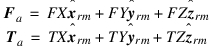
■Fa is the translational action applied to the I marker.
■FX is the user-defined function for the x-component force magnitude.
■FY is the user-defined function for the y-component force magnitude.
■FZ is the user-defined function for the z-component force magnitude.
■Ta is the rotational action applied to the I marker.
■TX is the user-defined function for the x-component according to the right-hand rule.
■TY is the user-defined function for the y-component according to the right-hand rule.
■TZ is the user-defined function for the z-component according to the right-hand rule.
■ is a unit vector along the + x-direction of the RM marker.
is a unit vector along the + x-direction of the RM marker. ■ is a unit vector along the + y-direction of the RM marker.
is a unit vector along the + y-direction of the RM marker. ■ is a unit vector along the + z-direction of the RM marker.
is a unit vector along the + z-direction of the RM marker. Reaction
Applied to: JFLOAT marker
Values:
Fr = -Fa
Tr = -Ta
where Fr and Tr are the translational and rotational reactions applied at the JFLOAT marker, respectively.
Tip: | Depending on the nature of the desired force relationship, the RM marker may belong to the same part as the I marker or JFLOAT marker, or to a third, unrelated part. |
Caution: | The user-defined forces FX, FY, FZ, TX, TY, and TZ should be smooth, continuous, and single-valued. These conditions make the solution process very effective. |
Examples
GFORCE/1, I=310, JFLOAT=9910, RM=310,
, FX = -20.*VX(310,9900,310)\
, FY = -20.*VY(310,9900,310)\
, FZ = -20.*VZ(310,9900,310)\
, TX = -6.*WX(310,9900,310)\
, TY = -6.*WY(310,9900,310)\
, TZ = -6.*WZ(310,9900,310)
, FX = -20.*VX(310,9900,310)\
, FY = -20.*VY(310,9900,310)\
, FZ = -20.*VZ(310,9900,310)\
, TX = -6.*WX(310,9900,310)\
, TY = -6.*WY(310,9900,310)\
, TZ = -6.*WZ(310,9900,310)
This GFORCE statement defines a general, six-component force acting between fixed Marker 310 and floating Marker 9910, which must belong to different parts. Expressions FX, FY, FZ, TX, TY, and TZ define the force and torque components the x, y, and z axes of the reference marker, which is Marker 310. Adams Solver (FORTRAN) superimposes floating Marker 9910 on Marker 310, and apply the reaction force and torque at that point.
Applications
The GFORCE statement is most useful when you need to define a vector force and vector torque whose point of application and/or direction is most easily formulated in a coordinate system which moves or is on a different part than the parts containing the force application points. For example, a GFORCE statement could be used to model the normal and friction force effects for a ball rolling down an inclined surface. See the figure below.
Model of Ball Rolling Down Incline
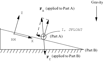
For this application, the RM reference marker would be fixed to the surface and would supply the orientation for the normal and friction forces and the torque about the ball center due to the friction.
When compared with the SFORCE (see SFORCE statement), the GFORCE statement can vary both its point of application (with respect to the part containing the JFLOAT marker) and its resultant direction (with respect to the RM-marker). In these cases, a single GFORCE statement can represent the complete force/torque condition at a point along with its reaction forces, whereas it would require six translational SFORCEs and six rotational SFORCEs, with appropriately-oriented markers, to accomplish the same thing.
See other Forces available.