BUSHING
The BUSHING statement defines a massless bushing with linear stiffness and damping properties.
Format
Arguments
C=r1,r2,r3 | Specifies three viscous damping coefficients for the force transferred by the bushing. The three coefficients multiply the relative translational velocity components of the I marker with respect to the J marker as seen by the J marker and along the x-, y-, and z-axis of the J marker. The force due to damping is zero when there is no relative translational velocity between the two markers. C must be in units of force-time per unit displacement. Default: 0,0,0 Range:  |
CT=r1,r2,r3 | Specifies three viscous damping coefficients for the torque transferred by the bushing. The three coefficients multiply the components of the relative angular velocity of the part containing the I marker with respect to the part containing the J marker as expressed in the x-, y-, and z-axis of the J marker. The torque due to damping is zero when there is no relative angular velocity between the two markers. CT must be in units torque-time per radian. Default: 0,0,0 Range:  |
FORCE=r1,r2,r3 | Specifies three constant force (preload) values. Constant values indicate the force components along the x-, y-, and z-axis of the J marker when both the relative displacement and the relative velocity of the I and J markers are zero. Default: 0,0,0 |
I=id, J=id | Specifies the identifiers of the two markers between which the bushing is placed. |
K=r1,r2,r3 | Specifies three stiffness coefficients for the force transferred by the bushing. The three coefficients multiply the three translational displacement components of the I marker with respect to the J marker as expressed in the x-, y-, and z-axis of the J marker. K must be specified in terms of force per unit of deformation. Default: 0,0,0 Range:  |
KT=r1,r2,r3 | Specifies three stiffness coefficients for the torque transferred by the bushing. The three coefficients multiply the three rotational displacement components of the I marker axes relative to the J marker axes as expressed in the x-, y-, and z-axis of the J marker. KT must be in units of torque per radian. Default: 0,0,0 Range:  |
TORQUE=r1,r2,r3 | Specifies three constant torque (preload) values. Constant values indicate the torque components about the x-, y-, and z-axis of the J marker when both the relative displacement and the relative velocity of the I and the J markers are zero. Default: 0,0,0 |
Extended Definition
The BUSHING statement defines a massless bushing with linear stiffness and damping properties. The BUSHING statement applies a force and torque to two parts. You specify a marker on each part for force and/or torque application.
Each force consists of three components in the coordinate system of the J marker, one in the x-axis direction, one in the y-axis direction, and one in the z-axis direction.
Likewise each torque consists of three components in the coordinate system of the J marker: one about the x-axis, one about the y-axis, and one about the z-axis. The force is linearly dependent upon the relative displacement and the relative velocity of the two markers. The torque is dependent upon the relative angle of rotation and the relative rotational velocity of the parts containing the specified markers.
A BUSHING statement has the same constitutive relation form as a FIELD statement. The primary difference between the two statements is that certain coefficients (Kij and Cij, where i  j) are zero for the BUSHING statement. Only the diagonal coefficients (Kii and Cii) are defined for a BUSHING.
j) are zero for the BUSHING statement. Only the diagonal coefficients (Kii and Cii) are defined for a BUSHING.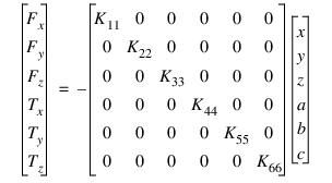
Fx, Fy, and Fz are the measure numbers of the translational force components in the coordinate system of the J marker. The terms x, y, and z are the translational displacements of the I marker with respect to the J marker measured in the coordinate system of the J marker. The terms Vx, Vy, and Vz are the time derivatives of x, y, and z, respectively. The terms F1, F2, and F3 represent the measure numbers of any constant preload force components in the coordinate system of the J marker.
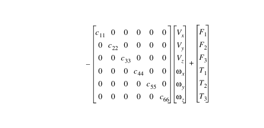
Tx, Ty, and Tz are the rotational force components in the coordinate system of the J marker. The terms a, b, and c are the relative rotational displacements of the I marker with respect to the J marker as expressed in the x-, y-, and z-axis, respectively, of the J marker. The terms  ,
,  , and
, and  are the angular velocity components of the I marker with respect to the J marker, measured in the coordinate system of the J marker. The terms T1, T2, and T3 are the measure numbers of any constant torque in the coordinate system of the J marker.
, , and are the angular velocity components of the I marker with respect to the J marker, measured in the coordinate system of the J marker. The terms T1, T2, and T3 are the measure numbers of any constant torque in the coordinate system of the J marker.Adams Solver (C++) applies an equilibrating force and torque to the J marker, as defined by the following equations:
Fj=-Fi
Tj = - Ti -  x Fi
x Fi
x Fi is the instantaneous deformation vector from the J marker to the I marker. While the force at the J marker is equal and opposite to the force at the I marker, the torque at the J marker is usually not equal to the torque at the I marker because of the deformation.
The BUSHING only models linear bushings. The GFORCE or FIELD (with a FIESUB) may be used to model nonlinear bushings.
Caution: | For the rotational constitutive equations to be accurate, at least two of the rotations (a, b, c) must be small. That is, two of the three values must remain smaller than 10 degrees. In addition, if a becomes greater than 90 degrees, b becomes erratic. If b becomes greater than 90 degrees, a becomes erratic. Only c can become greater than 90 degrees without causing convergence problems. For these reasons, it is best to define your bushing such that angles a and b (not a and c and not b and c) remain small. a, b, c mentioned here are the three rotational displacements that define the bushing and not Euler angles. They are the projected angles of the I marker with respect to the J marker. Adams Solver (C++) measures them respectively, about the x-, y-, and z-axis of the J marker. By definition, a BUSHING element is asymmetric. Holding the J marker fixed and deflecting the I marker produces different results from holding the I marker fixed and deflecting the J marker by the same amount. This asymmetry occurs because the coordinate system frame that the deflection of the bushing is measured in, moves with the J marker. This asymmetry is similar to other force elements like BEAM. Here are some best practices that will help avoid the effects of asymmetry for the BUSHING element. 1. Be sure to follow the above recommendation on rotations. Projection angles a (about X) and b (about Y) should be small (less than 10 degrees) in order for the rotational constitutive equations to be somewhat accurate. 2. The closer I and J marker are in location the better so that the moment arm and hence reaction torque is small. Note that even if markers I and J are coincident the bushing may start to behave asymmetrically due to deflection of the bushing. 3. Consider splitting the BUSHING into two elements that reference the same two markers, one with markers I and J defined in reverse from the other. Also, you will need to divide by two the properties such as stiffness of the original bushing since the two bushings will be in parallel. This would provide symmetry to the forces since the reaction torque would be applied equally to both sides. See the example below. |
Examples
BUSHING/1022, I=10, J=22, K=5000,5000,2000, C=5,5,2
, KT=50000,50000,0, CT=50,50,0
, KT=50000,50000,0, CT=50,50,0
This BUSHING statement describes a bushing with translational spring rates of 5000 units in both the x-axis and the y-axis directions of Marker 22 and of 2000 units in the z-axis direction of Marker 22. The corresponding damping rates for the force are 5 units in both the x- and y-axis directions of Marker 22 and 2 units in the z-axis direction of Marker 22. The rotational spring rates are 50000 units about the x- and y-axis of Marker 22. The corresponding damping rates for the torque are 50 units in both the x- and y-axis directions of Marker 22 and zero units in the z-axis direction of Marker 22. Since the z components of KT and CT are zero, the I marker can rotate about the z-axis of the J marker without generating any torque. There are no FORCE or TORQUE values because there is no initial load (preload) associated with the input positions of the markers.
BUSHING/1023, I=10, J=22, K=2500,2500,1000, C=2.5,2.5,1
, KT=25000,25000,0, CT=25,25,0
, KT=25000,25000,0, CT=25,25,0
BUSHING/1024, I=22, J=10, K=2500,2500,1000, C=2.5,2.5,1
, KT=25000,25000,0, CT=25,25,0
, KT=25000,25000,0, CT=25,25,0
These two BUSHING statements provide equivalent quantity rates as the BUSHING in the first example while overcoming modeling asymmetry by design as mentioned in the cautionary note above. This example results in symmetrical forces at markers 10 and 22.
See other Forces available.