FEMDATA
The FEMDATA statement produces data files of component loads, deformations, stresses, or strains for input to subsequent finite element or fatigue life analysis. Also, FEMDATA can be used to output monitor point time histories, if monitor point data is provided in the MNF.
You use the OUTPUT statement to specify the type of file FEMDATA produces. Except for HOTSPOTS table and the old style (.fem) file, FEMDATA will not output data to any files unless you specify the format in the OUTPUT statement.
Format
Arguments
CRITERION = c | Specifies the criterion or value of stress or strain in determining hot spots. Supported criteria are one of: VON_MISES, MAX_PRIN, MIN_PRIN, MAX_SHEAR, NORMAL_X, NORMAL_Y, NORMAL_Z, SHEAR_XY, SHEAR_YZ, SHEAR_XZ, and SIGNED_VON_MISES. Default criterion is VON_MISES. |
DATUM = node_id | Specifies a node ID of the flexible body to be the datum of the nodal displacements. Adams Solver computes all nodal displacements relative to this node ID. If you do not specify a datum node, Adams Solver generates an arbitrary relative set of nodal displacements. It displays a warning message if the specified node does not belong to the flexible body. |
END = t2 | Specifies the time, t2, at which to end the output of the data or the search of a peak load. Default: Output or search to the end of the simulation. Range: t2 > t1 |
HOTSPOTS = n | Specifies the number of hot spots to locate and output on the flexible body or fe part. A search for the top n locations (nodes or markers) that recorded the highest stress or strain during the simulation will ensue. With the START, END or SKIP arguments, FEMDATA only checks the time steps within those specifications for hot spots. A text file containing a table of hot-spot data (node/marker ID, maximum value, time of maximum value, and location) will be output. The complete time history of stress or strain will be output as well for each hot spot, if the STRAIN or STRESS option is specified in the OUTPUT statement. |
FE_PART = id | Specifies the ID of the fe part whose data FEMDATA outputs. FEMDATA outputs the data in the body coordinate system for the FE Part (LPRF), except in the case of STRAIN or STRESS with the RM = id option. |
FLEX_BODY = id | Specifies the ID of the flexible body whose data FEMDATA outputs. FEMDATA outputs the data in the FEM basic coordinate system that is inherent to the flexible body, except in the case of STRAIN or STRESS with the RM = id option. |
FILE = name | Specifies the output file name for the FEM data. You can specify an existing directory, root name, and/or extension. By default, the file name will be composed of the ADAMS run and body IDs according to the type of data and file format that you specified in the OUTPUT statement. |
LOADS | Outputs all external forces (reaction and applied forces except gravity) acting on the specified body and inertial forces of the specified body (angular velocities and accelerations including effects of gravity) as a function of time. Load data will be output in the simulation set of units. |
MARKER = id1 [,…,idn] | Specifies the marker id(s) of a fe part whose data is to be output. Adams Solver issues a warning if a marker ID is specified that does not belong to the fe part. |
MONITOR_POINTS | Outputs monitor point time histories for the specified flexible body if monitor point data blocks exist in the MNF of the flex body. |
MODAL_DEFORMATION | Outputs modal deformations as a function of time of the specified flexible body. FEMDATA will only export coordinates of the active modes in the simulation. |
NODAL_DEFORMATION | Outputs nodal deformations as a function of time of the specified flexible. FEMDATA writes the formations in the simulation set of units. |
NODE = id1 [,…,idn] | Specifies the node numbers of a flexible body whose data is to be output. If you do not specify a node list, FEMDATA exports nodal data at each attachment point of the flexible body. Adams Solver issues a warning if a node ID is specified that does not belong to the flexible body. |
NOINERTIA | Turns off the output of inertia loads. Inertia loads include linear acceleration, angular acceleration, and angular velocity of the part or flexible body. Only loads due to reaction and applied forces are output with this option. This results in a load imbalance specification for the body, so you must employ a technique, such as inertia relief, to recover the inertia loads from the external loads in the finite element program. |
PEAK_SLICE = FX:FY:FZ:FMAG:GMAG: TX:TY:TZ:TMAG | Specifies that FEM load data are to be output only at those time steps where the specified peak load occurred in the simulation. With the START, END, or SKIP arguments, FEMDATA only checks the time steps within those specifications for the peak load. You can specify one or more of FX, FY, FZ, FMAG, GMAG, TX, TY, TZ, TMAG. |
RADIUS = r | Specifies a radius between hot spots. If specified, all locations (nodes or markers) falling within a sphere defined by radius r and centered about the location with the highest stress/strain, will be considered one hot spot. A default value of zero means that all locations for the flexible body or fe part are candidates for hot spots. |
RM = id | Specifies the rigid body marker to be the reference coordinate system to output loads. Because Adams Solver resolves all loads acting on the rigid body in the coordinate system of the specified marker, the marker should represent the FEA basic coordinate system of the part's finite element model (FEM). If only RM is specified with no accompanying type (that is, LOADS or STRESS or STRAIN), an old style .fem file is generated with loading information for each rigid body that has a marker listed on this field. For STRESS or STRAIN, optionally specifies the reference coordinate system in which to output. If RM is not specified, stress/strain will be computed in the flexible body or fe part's LPRF. If specified, the stress/strain tensor will be transformed relative to instantaneous coordinate system of marker ID. The RM does not have to belong to the flexible body or fe part, but can be any marker in the model. All six components of stress or strain (Sxx, Syy, Szz, Sxy, Syz, Szx) can be affected by this coordinate transformation. This option can be useful when correlating test results such as strain gauge data on a flexible component. |
SKIP = n | Specifies the number of output steps to skip when outputting the data. Default: n=0 (every step is output). |
START = t1 | Specifies the time at which to start outputting the data. Default: Output at the start of the simulation. Range: t1 > t2 (See END argument) |
STRAIN | Outputs strain information to fe part or flex body if strain modes are available in the modal neutral file (MNF) of the specified flexible body. FEMDATA outputs all six components of strain (normal-X, normal-Y, normal-Z, shear-XY, shear-YZ, shear-ZX). It outputs strains in the basic FEA coordinate system of the flexible body or LPRF of fe part, unless the RM = id option is specified. |
STRESS | Outputs stress information to fe part or flex body if modal stresses are available in the MNF of the flexible body. FEMDATA outputs all six components of stress (normal-X, normal-Y, normal-Z, shear-XY, shear-YZ, shear-ZX). It outputs stresses output in the simulation set of units in the basic FEA coordinate system of the flexible body or LPRF of fe part, unless the RM = id option is specified. |
Extended Definition
Default File Naming Conventions
You can use the FILE argument to specify the directory, name, and/or extension (directory/name.extension) for the output file. If you do not specify a directory, FEMDATA creates all its output files except DAC files in the current working directory. Because several DAC files are typically generated for a FEMDATA statement, FEMDATA creates them in a separate directory named after the body. It creates this directory in the current working directory if it does not exist.
If a file name is not specified in the FILE argument, default file names are assigned according to the type of FEM data and file format (which is specified in the OUTPUT statement) as shown in the table below.
FEMDATA Default File Names and Extensions
Type of data: | Format:* | File name: | Extension: |
|---|---|---|---|
(none) | (none) | <run_name> | .fem |
Loads | DAC NASTRAN ABAQUS ANSYS RPC | <run_name>_<channel_id> <run_name>_<body_name> <run_name>_<body_name> <run_name>_<body_name> <run_name> | .dac .dat .dat .dat .rsp |
Modal Deformation | DAC Generic NASTRAN PUNCH ANSYS RPC | <run_name>_<channel_id> <run_name>_<body_name <run_name>_<body_name> <run_name>_<body_name> <run_name> <run_name> | .dac .mdf .mdf .mdf .out .rsp |
Nodal Deformation | Generic NASTRAN ANSYS | <run_name>_<body_name> <run_name>_<body_name> <run_name>_<body_name> | .ndf .spc .inp |
Strain | DAC Generic RPC | <run_name>_<node_id>e_<channel_id> <run_name>_<body_name> <run_name>_<body_name> | .dac .nsf .rsp |
Hotspots | <run_name>_body_name>_hots | .tab | |
Monitor Points | CSV Generic RPC | <run_name>_<body_name> <run_name>_<body_name> <run_name>_<body_name> | .csv .req .rsp |
Stress | DAC Generic RPC | <run_name>_<node_id>se_<channel_id> <run_name>_<body_name> <run_name>_<body_name> | .dac .nsf .rsp |
Hotspots | <run_name>_<body_name>_hote | .tab |
*Specified in the OUTPUT statement
Old Style FEMDATA
An older version of the FEMDATA statement where one or more RM markers are specified with no data type is still being supported. The format of this version of FEMDATA is:
FEMDATA/id, RM=id1[,...,id100]
In this case, a text file with extension .fem is generated. This file contains generic load specifications for the parent body of each RM marker specified.
Format of .fem File
The .fem file contains information sufficient to define all forces (inertial and applied) acting on one or more parts. The data in this file is intended to be converted to boundary conditions input to a finite element program. This file is composed of the following lines:
Line1: <Header>
Line 2: <Title>
Lines repeated for every part:
Lines repeated for every output step:
<Record 1> (RM Displacement)
<Record 2> (CM Displacement)
<Record 3> (CM Velocity)
<Record 4> (CM Acceleration)
<Record 5> (Force Displacement)
<Record 6> (Force Values)
Line 2: <Title>
Lines repeated for every part:
Lines repeated for every output step:
<Record 1> (RM Displacement)
<Record 2> (CM Displacement)
<Record 3> (CM Velocity)
<Record 4> (CM Acceleration)
<Record 5> (Force Displacement)
<Record 6> (Force Values)
<Header> Definition
Output: File Version #, Date&Time, User ID, Job ID, Program ID
Format: 1X, A4, 4X, A18, 6X, 2I10, 2X, A2
Output: File Version #, Date&Time, User ID, Job ID, Program ID
Format: 1X, A4, 4X, A18, 6X, 2I10, 2X, A2
<Title> Definition
Output: Title of ADAMS run
Format: A80
<Record 1> Definition - RM Location
Output: Part ID, Time, 1, X, Y, Z, <Euler Angles (radians)>, RM ID
Format: I10, 1PE13.5, I2, 6(1PE13.5), I10
Output: Title of ADAMS run
Format: A80
<Record 1> Definition - RM Location
Output: Part ID, Time, 1, X, Y, Z, <Euler Angles (radians)>, RM ID
Format: I10, 1PE13.5, I2, 6(1PE13.5), I10
<Record 2> Definition - CM Location wrt RM
Output: Part ID, Time, 2, X, Y, Z, <Euler Angles (radians)>, CM ID
Format: I10, 1PE13.5, I2, 6(1PE13.5), I10
Output: Part ID, Time, 2, X, Y, Z, <Euler Angles (radians)>, CM ID
Format: I10, 1PE13.5, I2, 6(1PE13.5), I10
<Record 3> Definition - CM Velocity wrt RM
Output: Part ID, Time, 3, X’, Y’, Z’, Wx, Wy, Wz(radians/time), CM ID
Format: I10, 1PE13.5, I2, 6(1PE13.5), I10
Output: Part ID, Time, 3, X’, Y’, Z’, Wx, Wy, Wz(radians/time), CM ID
Format: I10, 1PE13.5, I2, 6(1PE13.5), I10
<Record 4> Definition - CM Acceleration wrt RM
Output: Part ID, Time, 4, X’’, Y’’, Z’’, Wx’, Wy’, Wz’(radians/time**2), CM ID
Format: I10, 1PE13.5, I2, 6(1PE13.5), I10
Output: Part ID, Time, 4, X’’, Y’’, Z’’, Wx’, Wy’, Wz’(radians/time**2), CM ID
Format: I10, 1PE13.5, I2, 6(1PE13.5), I10
<Record 5> Definition – External Force Location wrt RM
Output: Part ID, Time, 5, X, Y, Z, <Euler Angles (radians)>, Marker ID
Format: I10, 1PE13.5, I2, 6(1PE13.5), I10
Output: Part ID, Time, 5, X, Y, Z, <Euler Angles (radians)>, Marker ID
Format: I10, 1PE13.5, I2, 6(1PE13.5), I10
<Record 6> Definition – External Force Record wrt RM
Output: Part ID, Time, 3, Fx, Fy, Fz, Tx, Ty, Marker ID
Format: I10, 1PE13.5, I2, 6(1PE13.5), I10
Output: Part ID, Time, 3, Fx, Fy, Fz, Tx, Ty, Marker ID
Format: I10, 1PE13.5, I2, 6(1PE13.5), I10
Peak Loads
Except for FMAG, GMAG, and TMAG, each PEAK_SLICE load specification (FX, FY, FZ, TX, TY, TZ) generates two output time steps for each marker force of the component, one for the maximum (peak) and one for the minimum (valley). For FMAG and TMAG, only one time step is output for each marker force since these quantities are load magnitudes and generate only positive values. With GMAG, only one time step is output per body. If:
■Fm(t) represents the force acting on the body at Marker m.
■ represents the unit vector of the reference coordinate system of the rigid body (FEA coordinate system of the flexible body).
represents the unit vector of the reference coordinate system of the rigid body (FEA coordinate system of the flexible body).■r(t) represents the position of the reference marker (RM) in that coordinate system.
■|| || represents taking the magnitude or length of a vector (that is, || (  ) || = 1)
) || = 1)Then the following conditions apply:
■FX = Output loads at time t when  is a maximum and minimum for each marker m.
is a maximum and minimum for each marker m.■FY = Output loads at time t when  is a maximum and minimum for each marker m.
is a maximum and minimum for each marker m.■FZ = Output loads at time t when  is a maximum and minimum for each marker m.
is a maximum and minimum for each marker m.■FMAG = Output loads at time t when  is a maximum for each marker m.
is a maximum for each marker m.■GMAG = Output loads at time t when
■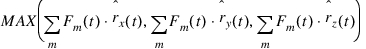 .
.
.Note: | Similar expressions exist for TX, TY, TZ, and TMAG. The PEAK_SLICE argument is not available when you specify a time history OUTPUT load format (DAC or RPC). |
Modal Superposition
Nodal displacements, strains, and stresses are computed using the principal of modal superposition:
Here  i are the respective mode shapes from FEA and {q(t)}are the modal displacements of the flexible body that Adams Solver computes.
i are the respective mode shapes from FEA and {q(t)}are the modal displacements of the flexible body that Adams Solver computes.Coordinate Reference Transformation of Stress or Strain
Because stress and strain are second-order tensors, the following equation is used to transform these quantities to a reference coordinate system:
Where  is the skew-rotation matrix from the flexible body’s LPRF (FE origin) to the marker’s coordinate reference, and
  is the symmetric stress or strain tensor. That is:
is the skew-rotation matrix from the flexible body’s LPRF (FE origin) to the marker’s coordinate reference, and is the symmetric stress or strain tensor. That is: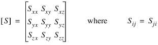
Definition of Hot Spots
The figure below illustrates how the radius argument can affect the definition of a hot spot region. In this figure, the top 7 hottest nodes (those with the largest stress) are listed. If the number 5 and no radius is specified on HOTSPOTS, then only nodes 4, 5, 3, 6, and 2 would be output. If a radius of 0.5 mm is specified, then only node 4 would be listed from this region and the other 4 hot spots would come from nodes with the highest stress from other regions.
Limitations
Using FEMDATA to output loads encounters the same limitations as exporting FEA Loads in Adams View. See Limitations for Exporting FEA Loads for more information.
Caution: | Note that all FEMDATA are output in the Adams modeling units. This causes a problem when the Adams units are inconsistent with those used in the finite element model, and the data that is output will be included in a subsequent finite element analysis. For example, when outputting FEMDATA of type LOADS to ANSYS or MSC.Nastran for inclusion in the FE analysis, the Adams and FE modeling units must be consistent. This is also true when outputting FEMDATA of type NODAL_DEFORMATION when the OUTPUT format is ANSYS or MSC.Nastran and the data will be used as input to the FE analysis. In the case of outputting FEMDATA of type MODAL_DEFORMATION, the only concern for units is when MSC.Nastran (or PUNCH) has been specified as the OUTPUT format. This is because rigid body motion is included in the output file along with the modal coordinates. By definition, modal coordinates are unitless, so the modal stresses (or strains) will be recovered correctly in MSC.Nastran irregardless of unit settings. However, in order for the overall displacement of the component to be correctly recovered, the unit of length must be consistent between models. |
Examples
FEMDATA/100, STRESS, FLEX_BODY=101
, HOTSPOTS = 7, CRITERION = MAX_PRIN
, RADIUS = 0.5, FILE = hotspots_101
OUTPUT/STRESS = DAC
These statements create a text file, named hotspots_101.tab containing hot spot information for flexible body 101. Seven hot spots with a radius of 0.5 based on maximum principal stress are requested. Also, a time history of the stress for each node found to be a hot spot is output in DAC format. The names of the DAC files are given the prefix “hotspots_101” as specified in the FILE argument.
FEMDATA/1, LOADS, RM=201
, PEAK_SLICE = GMAG
, FILE = peak201.nas
OUTPUT/LOADS = NASTRAN
, PEAK_SLICE = GMAG
, FILE = peak201.nas
OUTPUT/LOADS = NASTRAN
These statements create a NASTRAN input file containing loads of the parent part of marker 201 in that marker’s coordinate reference system. They output the loads for only one time step when the magnitude of the global sum of all marker forces on the part is greatest in the simulation.
FEMDATA/2, LOADS, FLEX_BODY=101
, PEAK_SLICE = FX:FY:FZ:FMAG
OUTPUT/LOADS = ANSYS
These statements create an ANSYS input file with .dat default extension containing loads acting on flexible body 101 in the FEA coordinate system. If the flexible body has, say 4 attachments, you should expect (3*2 + 1)*4 load cases (loads from 28 time steps) to be output, because FX, FY and FZ output loads for 2 time steps per attachment, and FMAG will output 1 per attachment.
FEMDATA/100, LOADS, FLEX_BODY=101
, FILE = conrod
OUTPUT/LOADS = RPC
These statements create an RPC file, named conrod.rsp that contains the time history of loads for all load channels acting on flexible body 101. A Nastran load map file is also generated, named conrod_lc.nas. This file contains the unit loads definitions in Nastran input format that map to the load channels in the RPC file. This file can be combined with the Nastran BDF that was used to define the flexible body’ mesh, and perform a static solution in obtaining stress coefficients related to the unit loads. The stress coefficients can be combined with the actual loads in the RPC file in a fatigue program such as CAEfatigue or MSC.Fatigue to perform a fatigue analysis based on linear superposition theory.
See other Output available.