GEAR
The GEAR statement defines a gear pair constraint. Examples include a spur, helical, planetary, bevel, and rack-and-pinion gear pairs.
Format
GEAR/id, JOINTS=id1,id2, CV=id
Arguments
CV=id | Identifier of the marker that designates the point of contact and implicitly determines the ratio of the two gears. The z-axis of the CV marker must point in the direction of common velocity at the point of contact. The direction of common velocity is tangent to both pitch circles and would be normal to the tooth surfaces of the gears if the pressure angle was zero (Adams Solver (C++) always assumes a zero pressure angle). The CV marker must belong to the carrier part that also hosts the J markers of the joints. |
JOINTS=id1,id2 | Specifies the two joints whose relative motion is to be related with a gear. Each of these two joints must be translational, revolute, or cylindrical. Note that both J markers of these joints belong to a carrier part that must also host the CV marker. |
Extended Definition
The GEAR statement uses the location of a common velocity CV marker to determine the point of contact of the two gear pitch circles. The direction of the z-axis of the common velocity marker indicates the direction of the common velocity of points on the gear teeth in contact. This is also the direction in which gear tooth forces act. Note that the CV marker has constant position and orientation in the carrier body coordinate system (BCS). The CV marker through its z-axis only provides a direction, and there is no need to be more specific than this. In this context, there is no need to indicate things such as how the power flow occurs through the gear.
The reaction force reported back to you for a GEAR element is the reaction force measured on the J marker of the joint that is specified first in the GEAR definition. It is important to keep in mind that the J markers for both joints associated with the GEAR element must belong to the carrier part (the part that hosts the CV marker).
Caution: | ■Gear reaction forces and torques are difficult to obtain from the Request file because of the way Adams Solver (C++) generates REQUEST statement output. Both joints associated with the gear resist the tooth force generated by the gear. Therefore, the gear tooth reaction force appears in both joints. The reaction torques due to the gear does not appear in the joints, but they can be calculated from the gear tooth reaction force and the moment arms to the joints. The Results file explicitly gives the gear tooth reaction force. ■A GEAR statement does not simulate the backlash and the other intermittent effects that characterize actual gears. |
Examples
The figure below illustrates the use of a GEAR statement to define a bevel gear pair.
Bevel Gear Pair
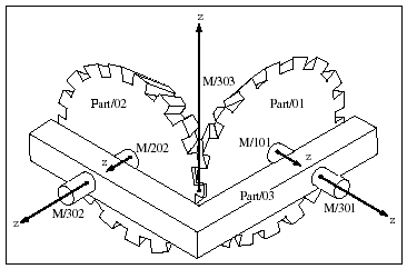
The GEAR statement for this gear pair is below.
GEAR/1, JOINTS=13,23, CV=303
This GEAR statement indicates that the gear pair relates the motions of Joints 13 and 23 and indicates the common velocity marker. Below are the statements that work with this GEAR statement to communicate the characteristics of the gear pair to Adams Solver (C++).
MARKER/303, PART=3, QP=-2, -2, 0
JOINT/13, I=101, J=301, REVOLUTE
MARKER/101, PART=1, QP=-10, 0, 0
, REULER=0, -90D, 0
MARKER/301, PART=3, QP=-10, 0, 0
, REULER=0,-90D, 0
JOINT/23, I=202, J=302, REVOLUTE
MARKER/202, PART=2, QP=0, -10, 0
, REULER=90D, 90D, 0
MARKER/302, PART=3, QP=0,-10,0
, REULER=90D,90D,0
JOINT/13, I=101, J=301, REVOLUTE
MARKER/101, PART=1, QP=-10, 0, 0
, REULER=0, -90D, 0
MARKER/301, PART=3, QP=-10, 0, 0
, REULER=0,-90D, 0
JOINT/23, I=202, J=302, REVOLUTE
MARKER/202, PART=2, QP=0, -10, 0
, REULER=90D, 90D, 0
MARKER/302, PART=3, QP=0,-10,0
, REULER=90D,90D,0
From JOINT statements 13 and 23, Adams Solver (C++) can determine that the first gear is Part 1 and that it forms a revolute joint with the carrier, which is Part 3. Adams Solver (C++) can also determine that the second gear is Part 2 and that it also forms a revolute joint with the carrier. MARKER statement 303 defines the location of the common velocity marker.
The following figure is a schematic of a rack-and-pinion gear pair.
Rack-and-Pinion Gear Pair
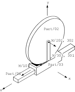
For this gear pair, the same GEAR statement is used as the one in the previous example, but a different set of JOINT and MARKER statements communicate characteristics of the gear to Adams Solver. Those statements are as follows:
MARKER/303, PART=3, QP=0,0,0
JOINT/13, I=101, J=301, TRANSLATIONAL
MARKER/101, PART=1, QP=0,0,0
MARKER/301, PART=3, QP=0,0,0
JOINT/23, I=202, J=302, REVOLUTE
MARKER/202, PART=2, QP=0,10,0
, REULER=90D,90D,0
MARKER/302, PART=3, QP=0,10,0
, REULER=90D,90D,0
JOINT/13, I=101, J=301, TRANSLATIONAL
MARKER/101, PART=1, QP=0,0,0
MARKER/301, PART=3, QP=0,0,0
JOINT/23, I=202, J=302, REVOLUTE
MARKER/202, PART=2, QP=0,10,0
, REULER=90D,90D,0
MARKER/302, PART=3, QP=0,10,0
, REULER=90D,90D,0
In this example, JOINT statement 13 defines a translational joint rather than a revolute joint, and MARKER statement 303, which defines the constant velocity marker, has the same position and orientation as the ground coordinate system (GCS).
See other Constraints available.