NFORCE
The NFORCE statement creates a multi-point force element which establishes linear force-displacement (stiffness) and/or force-velocity (damping) relationships between many markers (up to 351) in the model.
Format
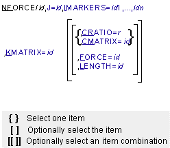
Arguments
CMATRIX=id | Specifies the identifier of the MATRIX that the NFORCE uses as its damping matrix. The CMATRIX is a  matrix (n is the number of I markers) that defines the linear relationships between the I marker velocities relative to the J marker and the viscous forces generated by the NFORCE. The CMATRIX is derived in the J marker’s coordinate system. If neither CMATRIX nor CRATIO is given, the NFORCE is undamped. Marker translational and rotational velocities appear sequentially in Vx, Vy, Vz, matrix (n is the number of I markers) that defines the linear relationships between the I marker velocities relative to the J marker and the viscous forces generated by the NFORCE. The CMATRIX is derived in the J marker’s coordinate system. If neither CMATRIX nor CRATIO is given, the NFORCE is undamped. Marker translational and rotational velocities appear sequentially in Vx, Vy, Vz,  x, x,  y, y,  z order, while the markers appear in the same sequence as in the IMARKER argument. z order, while the markers appear in the same sequence as in the IMARKER argument. |
CRATIO=r | Specifies the proportional damping ratio for the NFORCE. The elements of the damping matrix are determined by multiplying the corresponding stiffness element value by this number. If direct input of the damping properties is desired, the CMATRIX may be used. If neither CMATRIX nor CRATIO is given, the NFORCE is undamped. |
FORCE | Specifies the identifier of the MATRIX that contains the forces and torques that the NFORCE would produce if all the I markers were at the positions given in LENGTH. FORCE is a  matrix (n is the number of I markers) of forces and torques, appearing sequentially for each marker in Fx, Fy, Fz, Tx, Ty, Tz order, while the markers appear in the same sequence as in the IMARKER argument. The force and torque components are expressed in the J marker’s coordinate system. When LENGTH is used to specify the system’s free lengths, FORCE gives the preloads. If FORCE is not given, the NFORCE acts as though a matrix of zeros are input. matrix (n is the number of I markers) of forces and torques, appearing sequentially for each marker in Fx, Fy, Fz, Tx, Ty, Tz order, while the markers appear in the same sequence as in the IMARKER argument. The force and torque components are expressed in the J marker’s coordinate system. When LENGTH is used to specify the system’s free lengths, FORCE gives the preloads. If FORCE is not given, the NFORCE acts as though a matrix of zeros are input. |
IMARKERS=id1,...,idn | Lists the markers (except for the J marker) between which the NFORCE forces and torques act. Number of values: 1 to 350 |
J=id | Specifies the identifier of the marker that determines the reference frame in which the relative velocities and all of the forces associated with the NFORCE are calculated and the coordinate system in which all the components and LENGTHs are evaluated. The NFORCE automatically applies the proper reaction forces at the J marker. |
KMATRIX=id | Specifies the identifier of the MATRIX that the NFORCE uses as its stiffness matrix. The KMATRIX is a  matrix (n is the number of I markers) that defines the linear relationships between the I marker displacements relative to the J marker and elastic forces generated by the NFORCE. The KMATRIX is specified in the J marker’s coordinate system. Marker translational and rotational displacements appear sequentially in Dx, Dy, Dz, Ax, Ay, Az, order, while the markers appear in the same sequence as in the IMARKER argument. matrix (n is the number of I markers) that defines the linear relationships between the I marker displacements relative to the J marker and elastic forces generated by the NFORCE. The KMATRIX is specified in the J marker’s coordinate system. Marker translational and rotational displacements appear sequentially in Dx, Dy, Dz, Ax, Ay, Az, order, while the markers appear in the same sequence as in the IMARKER argument. |
LENGTH=id | Specifies the identifier of the MATRIX that defines a reference location for each of the I markers with respect to the J marker, measured in the J marker’s coordinate system. LENGTH is a  column matrix (n is the number of I markers) of translational displacements only, in Dx, Dy, Dz order. Usually, LENGTH is used to specify the system’s free (no internal force) lengths when they differ from the input positions. If LENGTH is not given, the NFORCE assumes that the input positions of the I markers are at the reference locations. column matrix (n is the number of I markers) of translational displacements only, in Dx, Dy, Dz order. Usually, LENGTH is used to specify the system’s free (no internal force) lengths when they differ from the input positions. If LENGTH is not given, the NFORCE assumes that the input positions of the I markers are at the reference locations. |
Extended Definition
The NFORCE creates a set of forces and torques which act between the I and J markers which appear in the NFORCE statement. These forces and torques are linear functions of the relative displacements and velocities of the markers, in a manner equivalent to the finite element method. For each NFORCE, one marker (J) is used as the reference marker. The velocities are resolved into the J marker’s reference frame and expressed in the J marker’s coordinate system. The force and torque components computed by the NFORCE are also given in the J marker’s coordinate system.
The force-displacement and force-velocity relationships are specified using stiffness and damping matrices, or by using a stiffness matrix and a proportional damping ratio. These matrices are defined using MATRIX statements in the dataset. The stiffness and damping matrices that Adams Solver requires are defined for the I markers only; that is, they should be derived normally using the 6(n+1) J marker and I marker degrees-of-freedom, but are input using only the rows and columns corresponding to the I marker degrees-of-freedom. This is equivalent, in finite element terminology, to applying fixed boundary conditions at the J marker by simply removing the corresponding rows and columns from the matrices. Adams Solver automatically computes and applies the correct reaction forces at the J marker.
Formulation
For n+1 points in the NFORCE system (n I markers and 1 J marker).
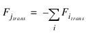
Action Forces (Forces on the I markers)
FI = - KMATRIX (X - L) - CMATRIX  + FORCE
+ FORCEwhere:
■FI is the  matrix of forces exerted on the I markers.
matrix of forces exerted on the I markers.■KMATRIX is the  truncated stiffness matrix, created by striking out the rows and columns associated with the J marker’s degrees-of-freedom.
truncated stiffness matrix, created by striking out the rows and columns associated with the J marker’s degrees-of-freedom.■X is the  matrix of the translational and angular displacements of the I markers with respect to the J marker, expressed in the J marker’s coordinate system.
matrix of the translational and angular displacements of the I markers with respect to the J marker, expressed in the J marker’s coordinate system.■L is a  matrix of the reference displacements of the I markers with respect to the J marker, expressed in the J marker’s coordinate system. The translational displacements in L are the elements of LENGTH, while the angular reference displacements are always zero.
matrix of the reference displacements of the I markers with respect to the J marker, expressed in the J marker’s coordinate system. The translational displacements in L are the elements of LENGTH, while the angular reference displacements are always zero.■CMATRIX is the  truncated damping matrix, created by striking out the rows and columns associated with the J marker’s degrees-of-freedom.
truncated damping matrix, created by striking out the rows and columns associated with the J marker’s degrees-of-freedom.■ is the
  matrix of the translational and linearized angular velocities of the I markers with respect to the J marker, and expressed in the J marker’s coordinate system.
is the matrix of the translational and linearized angular velocities of the I markers with respect to the J marker, and expressed in the J marker’s coordinate system.■FORCE is the  matrix of the reference forces on the I markers; that is, the forces on the I markers when their displacements relative to the J marker are specified by L. When LENGTH contains the free lengths, FORCE is the preload.
matrix of the reference forces on the I markers; that is, the forces on the I markers when their displacements relative to the J marker are specified by L. When LENGTH contains the free lengths, FORCE is the preload.Reaction Forces (Forces on the J marker)
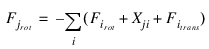
where:
■trans denotes translational degrees-of-freedom
■rot denotes rotational degrees-of-freedom
■Xji is the instantaneous vector from the J marker to each I marker.
Tip: | ■When importing stiffness and damping matrices that are developed using finite element methods, the LENGTH and FORCE arguments are most easily thought of as the system free lengths (zero internal stress) and preloads. You can, however, specify any consistent set of reference lengths and resulting forces, just as for the SPRINGDAMPER element. ■Physically meaningful NFORCES have positive semi-definite KMATRIX and CMATRIX matrices. That is, the diagonal entries of the matrices have positive value. Adams Solver only accepts NFORCES having positive semi-definite matrices. |
Caution: | ■Like the BEAM, the NFORCE is a linear element, so that the forces computed are generally valid only for small displacements. When the applied loading is such that the small displacement limits are exceeded (a good estimate is ten percent of lengths and less than 0.2 radian rotations), the NFORCE results may be less accurate. In cases where the structure undergoes large overall deflections but remains linearly elastic (small local deflections), you can use more NFORCE elements, so that each NFORCE element remains locally within small displacement limits. Note that because of the way that Adams Solver computes angular displacements, the absolute magnitude of this inaccuracy due to overly large displacement may depend on the instantaneous spatial orientation of the system. ■A two-point NFORCE is not identical to a field, although it is very similar. The following differences make it difficult to create exactly equivalent NFORCEs and FIELDs. ■The FIELD defaults reference lengths to zero, while the NFORCE assumes by default that the input positions of the I markers are at the reference locations. ■The FIELD allows you to specify reference angles for the rotational displacements, while the NFORCE assumes the reference angles are always zero. |
Examples
The figure below illustrates a simple, planar, triangular truss attached to some large base body.
Simple, Planar, Triangular Truss
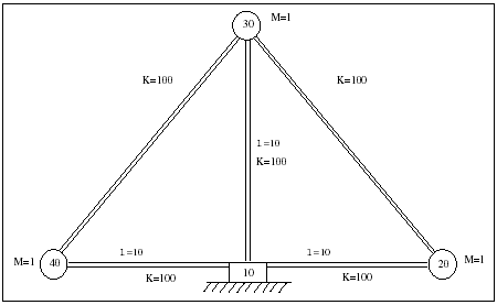
The following NFORCE statement defines a 24 force components acting between Markers 10, 20, 30, and 40.
NFORCE/1234, J=10, I=20,30,40, KMATRIX=1234, CRATIO=0.02
Marker 10 is the J marker. This means Matrix 1234 is an 18-by-18 stiffness matrix relating forces to displacements at Markers 20, 30 and 40. The forces and displacements are measured in the coordinate system of Marker 10. Because the LENGTH argument is not included, Adams Solver measures the displacements from the input position. Because the FORCE argument is not specified, there are no loads at the reference position (in this case the input position). In other words, the truss has been input in the unloaded, undeformed configuration. The damping matrix is .02 times the stiffness matrix.
Depending on the assumptions you make, the stiffness matrix for this structure could be quite elaborate. A simple case, however, is to assume the ends of the truss members are pinned, and that the truss members only transmit translational, in-plane forces.
Due to the simple geometry, this matrix can be determined by inspection, and is shown in the table shown next.
Simple Stiffness Matrix
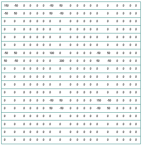
Because this matrix is mostly empty, the SPARSE option on the MATRIX statement is more convenient than listing all the matrix entries. The following MATRIX statement defines this stiffness matrix.
MATRIX/1234, SPARSE, ROW=18, COL=18,
, I=1,1,1,1,2,2,2,2,7,7,7,7,7,8,8,8,8,8,13,13,13,13,14,14,14,14,
, J=1,2,7,8,1,2,7,8,1,2,7,13,14,1,2,8,13,14,7,8,13,14,7,8,13,14,
, VALUE=150,-50,-50,50,-50,50,50,-50,-50,50,100,-50,50,
, 50,-50,200,50,-50,-50,50,150,-50,50,-50,-50,50
, I=1,1,1,1,2,2,2,2,7,7,7,7,7,8,8,8,8,8,13,13,13,13,14,14,14,14,
, J=1,2,7,8,1,2,7,8,1,2,7,13,14,1,2,8,13,14,7,8,13,14,7,8,13,14,
, VALUE=150,-50,-50,50,-50,50,50,-50,-50,50,100,-50,50,
, 50,-50,200,50,-50,-50,50,150,-50,50,-50,-50,50
Applications
The NFORCE statement may be most useful for importing finite element representations of flexible structure into an Adams Solver model, but it may also be used whenever the forces between a set of points in the system are linearly dependent on their relative displacements and velocities. If the set includes only two points, it is easily use one of the simpler Adams Solver force elements, SPRINGDAMPER, SFORCE, BEAM, BUSHING or FIELD, depending on the type of forces desired. However, whenever the set includes three or more points, you should use the NFORCE statement. (Note that some of the other force elements do allow for nonlinear force relationships.)
You may develop the NFORCE statement stiffness and damping matrices in several ways. For simple structures, you can derive the matrices analytically or compute them from standard formulas. For complex cases, you can use finite element analysis (FEA) to approximate the stiffness and damping characteristics.
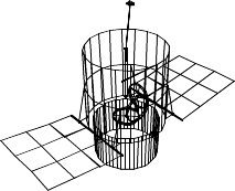
For example, the figure below illustrates a satellite deploying flexible panels. In this instance, the panels are first modeled using a  finite element grid (36 elements), which are then reduced to a
  grid using super-element condensation before importing it into Adams Solver as an NFORCE. Because of formulational differences between FEA and Adams’ multibody systems analysis, it is generally not possible to have a one-to-one correspondence between Adams Solver PARTs and FEA nodes, unless the FEA model is very small.
finite element grid (36 elements), which are then reduced to a grid using super-element condensation before importing it into Adams Solver as an NFORCE. Because of formulational differences between FEA and Adams’ multibody systems analysis, it is generally not possible to have a one-to-one correspondence between Adams Solver PARTs and FEA nodes, unless the FEA model is very small.Flexible Satellite Panels
See other Forces available.