output_control create femdata
Produces data files of component loads, deformations, stresses, or strains for input to subsequent finite element or fatigue life analysis for use in third party products. Adams View will not output to any files unless you specify the format.
Format:
output_control create femdata | |
|---|---|
femdata_name = | .model_name.femdata_name |
adams_id = | geom._id |
output_type = | loads/loads_on_flex/,odal_deformation/stress/strain |
r_marker_name = | .marker_name |
no_inertia = | yes/no |
peak_slice = | fx/fy/fz/fmag/gmag/tx/ty/tz/tmag/none/all |
fe_part = | .model_name.fe_part_name |
flex_body = | .model_name.flexible_body_name |
datum = | integer_number |
markers = | .marker_name |
nodes = | integer_number |
hotspots = | integer_number |
radius = | real _number |
criterion = | von_mises/max_principle/min_principle/max_shear/normal_x/normal_y/normal_z/shear_xy/shear_yz/shear_xz/signed_von_mises |
file_name = | file name |
start = | real_number |
end = | real_number |
skip = | integer_number |
Example:
Output_control create femdata & | |
|---|---|
femdata_name = | fem_data_1 & |
adams_id = | 100 & |
output_type = | stress & |
r_marker_name = | .marker_name & |
flex_body = | 101 & |
hotspots = | 7 & |
radius = | 0.5 & |
criterion = | max_principle & |
file_name = | hotspots_101 |
These statements create a text file named hotspots_101.tab containing hot spot information for the flexible body 101. Seven hot spots with a radius of 0.5 based on maximum principal stress are requested. The names of the DAC files are given the prefix “hotspots_101” as specified in the file_name format.
Description:
Parameter | Value Type | Description |
|---|---|---|
femdata_name | String | Specifies the name of the FEMDATA element in the modeling database to be created. |
adams_id | Integer | Specifies an integer used to identify this element in the Adams data file. |
output_type | loads/loads_on_flex/modal_deformation/stress/strain | Specifies the information you want as output: ■Loads on rigid body/Flex body - Output all external forces (reaction and applied forces except gravity) acting on the specified body and, optionally, inertial forces of the specified body (angular velocity and acceleration, including effects of gravity) as a function of time. Load data will be output in the simulation set of units. ■Modal Deformation - Outputs modal deformations as a function of time of the specified flexible body. Adams View will only export coordinates of the active modes in the simulation. ■Nodal Deformation - Outputs nodal deformations as a function of time of the specified flexible. Adams View writes the deformations in the simulation set of units. ■Strain - Outputs strain information if strain modes are available in the modal neutral file (MNF) of the specified flexible body and an Adams Durability license is available. Adams Durability outputs all six components of strain (normal-X, normal-Y, normal-Z, shear-XY, shear-YZ, shear-ZX). It outputs strains in the basic FEA coordinate system of the flexible body except where specified below. ■Stress - Outputs stress information if modal stresses are available in the MNF of the flexible body and an Adams Durability license is available. Adams Durability outputs all six components of stress (normal-X, normal-Y, normal-Z, shear-XY, shear-YZ, shear-ZX). It outputs stresses in the simulation set of units in the basic FEA coordinate system of the flexible body except where specified below. |
r_marker_name | String | Specifies the rigid body marker to be the reference coordinate system to output loads. Because Adams Solver resolves all loads acting on the rigid body in the coordinate system of the specified marker, the marker should represent the FEA basic coordinate system of the part's finite element (FE) model. |
no_inertia | yes/no | Specifies ‘yes’ for Adams View to include inertial loads (linear acceleration, angular acceleration, and velocity) when outputting the loads acting on the body. Otherwise, Adams View outputs no inertial loads and you will need to rely on an inertia relief capability in the finite element program to balance the external loads with the internal loads. |
peak_slice | fx/fy/fz/fmag/gmag/tx/ty/tz/tmag/none/all | Specifies that FE model load data are to be output only at those time steps where the specified peak load occurred in the simulation. When you set the Time options, Adams View only checks the time steps within those specifications for the peak load. |
flex_body | String | Enters the flexible body whose data Adams View outputs. Adams View outputs the data in the FE model basic coordinate system that is inherent to the flexible body. |
datum | Integer | Enters the node ID of the flexible body to be the datum of the nodal displacements. |
nodes | Integer | Enters the node numbers of a flexible body whose data is to be output. |
hotspots | Integer | Enters the number of hot spots to locate and output. With this option, a text file containing a tab-delimited table of hot spot information, such as node ID, maximum value, time when the maximum value occurred, and location, is generated. |
radius | Real | Enter a radius that defines the spherical extent of each hotspot. A default value of 0.0 (zero) means that all nodes in the flexible body will be hotspot candidates. |
criterion | von_mises/max_principle/min_principle/max_shear/normal_x/normal_y/normal_z/shear_xy/shear_yz,shear_xz | Specifies the value of stress/strain in determining hotspots from one of Von Mises, Max Prin., Min Prin., Max Shear, Normal-X, Normal-Y, Normal-Z, Shear-XY, Shear-YZ, or Shear-ZX. |
file_name | String | Enters the output file name for the FE model data. You can specify an existing directory, root name, and/or extension. By default, the file name will be composed of the Adams run and body IDs according to the type of data and file format that you specified in Solver -> Settings -> Output -> More -> Durability Files |
start | Real | Specifies the time at which to start outputting the data. The default is the start of the simulation. |
end | Real | Specifies the time at which to end the output of the data or the search of a peak load. The default is to output to the end of the simulation. |
skip | Integer | |
Extended Definition:
1. If you do not specify a node list, Adams View exports nodal data at each attachment point of the flexible body. Adams Solver issues a warning if a node ID is specified that does not belong to the flexible body.
2. Adams Solver computes all nodal displacements relative to the datum node ID. If you do not specify a datum node, Adams Solver generates an arbitrary relative set of nodal displacements. It displays a warning message if the specified node does not belong to the flexible body.
3. You can use the FILE_NAME argument to specify the directory, name, and/or extension (directory/name.extension) for the output file. If you do not specify a directory, FEMDATA creates all its output files except DAC files in the current working directory. Because several DAC files are typically generated for a FEMDATA statement, FEMDATA creates them in a separate directory named after the body. It creates this directory in the current working directory if it does not exist.
If a file name is not specified in the FILE argument, default file names are assigned according to the type of FEM data and file format (which is specified in the OUTPUT statement) as shown in the table below.
FEMDATA Default File Names and Extensions
Type of data | Format* | File name | Extension |
|---|---|---|---|
(none) | (none) | <run_name> | .fem |
Loads | DAC NASTRAN ABAQUS ANSYS RPC | <run_name>_<channel_id> <run_name>_<body_name> <run_name>_<body_name> <run_name>_<body_name> <run_name> | .dac .dat .dat .dat .rsp |
Modal Deformation | DAC Generic NASTRAN PUNCH ANSYS RPC | <run_name>_<channel_id> <run_name>_<body_name <run_name>_<body_name> <run_name>_<body_name> <run_name> <run_name> | .dac .mdf .mdf .mdf .out .rsp |
Nodal Deformation | Generic NASTRAN ANSYS | <run_name>_<body_name> <run_name>_<body_name> <run_name>_<body_name> | .ndf .spc .inp |
Strain | DAC Generic | <run_name>_<node_id>e_<channel_id> <run_name>_<body_name> | .dac .nsf |
Hotspots | <run_name>_body_name>_hots | .tab | |
Stress | DAC Generic | <run_name>_<node_id>se_<channel_id> <run_name>_<body_name> | .dac .nsf |
Hotspots | <run_name>_<body_name>_hote | .tab |
*Specified in the OUTPUT statement
4. Peak Loads
Except for FMAG, GMAG, and TMAG, each PEAK_SLICE load specification (FX, FY, FZ, TX, TY, TZ) generates two output time steps for each marker force of the component, one for the maximum (peak) and one for the minimum (valley). For FMAG and TMAG, only one time step is output for each marker force since these quantities are load magnitudes and generate only positive values. With GMAG, only one time step is output per body. If:
■Fm(t) represents the force acting on the body at Marker m.
■ represents the unit vector of the reference coordinate system of the rigid body (FEA coordinate system of the flexible body).
represents the unit vector of the reference coordinate system of the rigid body (FEA coordinate system of the flexible body).■r(t) represents the position of the reference marker (RM) in that coordinate system.
■|| || represents taking the magnitude or length of a vector (that is, || ( ) || = 1)
) || = 1)Then the following conditions apply:
■FX = Output loads at time t when  is a maximum and minimum for each marker m.
is a maximum and minimum for each marker m.■FY = Output loads at time t when  is a maximum and minimum for each marker m.
is a maximum and minimum for each marker m.■FZ = Output loads at time t when  is a maximum and minimum for each marker m.
is a maximum and minimum for each marker m.■FMAG = Output loads at time t when  is a maximum for each marker m.
is a maximum for each marker m.■GMAG = Output loads at time t when
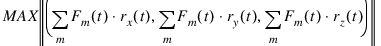
Note: | Similar expressions exist for TX, TY, TZ, and TMAG. The PEAK_SLICE argument is not available when you specify a time history OUTPUT load format (DAC or RPC). |
Caution:
1. Using FEMDATA to output loads encounters the same limitations as exporting FEA Loads in Adams View.
2. Note that all FEMDATA are output in the Adams modeling units. This causes a problem when the Adams units are inconsistent with those used in the finite element model, and the data that is output will be included in a subsequent finite element analysis.
For example, when outputting FEMDATA of type LOADS to ANSYS or MSC Nastran for inclusion in the FE analysis, the Adams and FE modeling units must be consistent. This is also true when outputting FEMDATA of type NODAL_DEFORMATION when the OUTPUT format is ANSYS or MSC Nastran and the data will be used as input to the FE analysis.
3. In the case of outputting FEMDATA of type MODAL_DEFORMATION, the only concern for units is when MSC Nastran (or PUNCH) has been specified as the OUTPUT format. This is because rigid body motion is included in the output file along with the modal coordinates. By definition, modal coordinates are unitless, so the modal stresses (or strains) will be recovered correctly in MSC Nastran irregardless of unit settings. However, for the overall displacement of the component to be correctly recovered, the unit of length must be consistent between models.