Creating Simple Cantilever
1. Start Adams View.
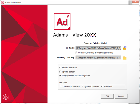
2. Select Existing Model from the startup screen.
The Open an Existing Model dialog box will appear.
3. Select the fe_part_example_start.cmd from “<topdir>\aview\examples\fe-part\” directory. For example, on a Windows installation for Adams version 20XX the example files are placed in the following location:
C:\Program Files\MSC.Software\Adams\20XX\aview\examples\fe-part\fe_part_example_start.cmd.
This model will only have a single green curve associate with ground.
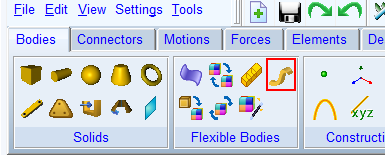
4. To launch the FE Part creation wizard, click the FE Part icon from the Flexible Bodies container on the Bodies of the ribbon
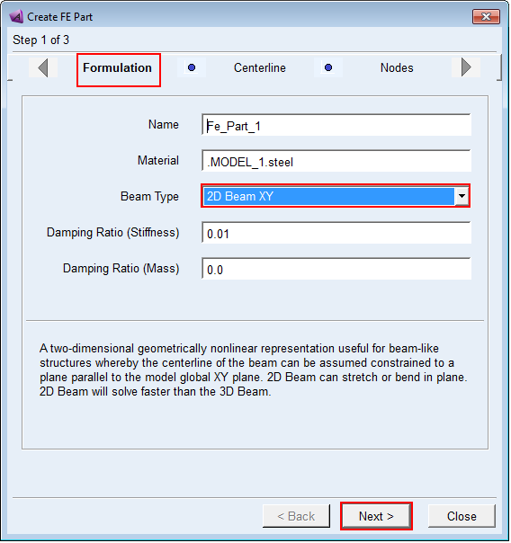
5. Select the 2D Beam XY formulation and click Next.
6. On the Centerline page select the curve GCURVE_1 already in the model:
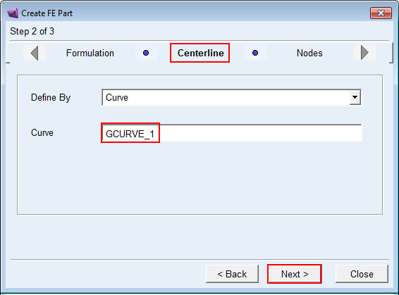
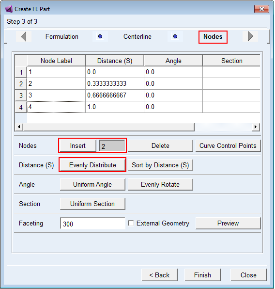
7. Click Next to proceed. On the Nodes page, select a row, then insert two rows into the table and click the “Evenly Distribute” button to equally space the 4 nodes along the length of the centerline. Click OK on the notification that all nodes’ S values will be overwritten.
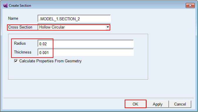
8. Right-click in the first row’s cell under the “Section” column, select “Create” and complete the dialog box as shown below and then click OK.
9. Back on the Nodes page of the FE Part wizard, click the Uniform Section button to assign the same cross-section to all nodes and click OK on the notification indicating that all nodes’ section definitions will be overwritten with this one.
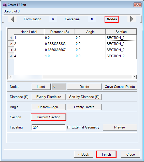
10. Click Finish and you will get a message describing that no solid geometry will be created, just a wire centerline. Click Close to acknowledge that message.
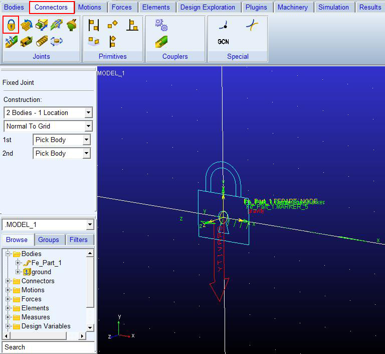
11. At the global origin create a fixed joint between the FE Part and ground.
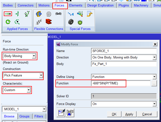
12. At the free end of the FE Part create a load in the global Y direction using a single component force. For the load function use “-600*SIN(PI*TIME)”
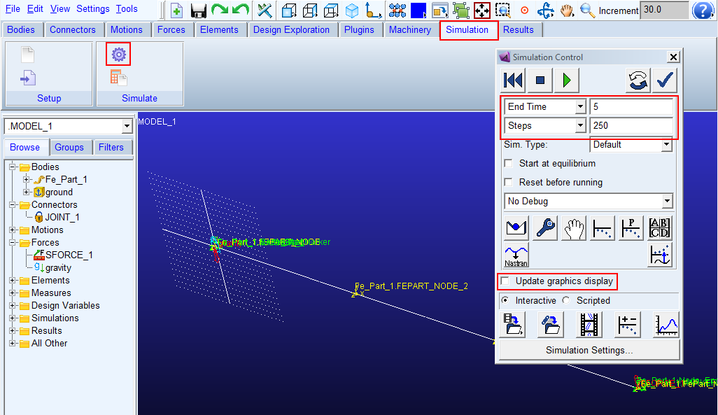
13. Run a 5 second simulation for 250 steps with “Update graphics display” off.
14. Open Adams PostProcessor.
15. Explore the results including the animation of the centerline geometry undergoing large deformation.