Building the Main Beam as an FE Part
1. Start Adams Car, and switch to the Template Builder.
2. Select File → Open → Template
3. Select the _NFE_twist_beam_FE_part.tpl from “<topdir>\acar\examples\fe-part\” directory. For example, on a Windows installation for Adams version 20XX the example files are placed in the following location:
C:\Program Files\MSC.Software\Adams\20XX\acar\examples\fe-part\_NFE_twist_beam_FE_part.tpl.
4. Click OK button to close the dialog box and load the model.
5. Select Build → Parts → FE Part → New and fill out the dialog box as follows:
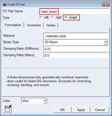
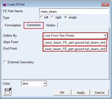
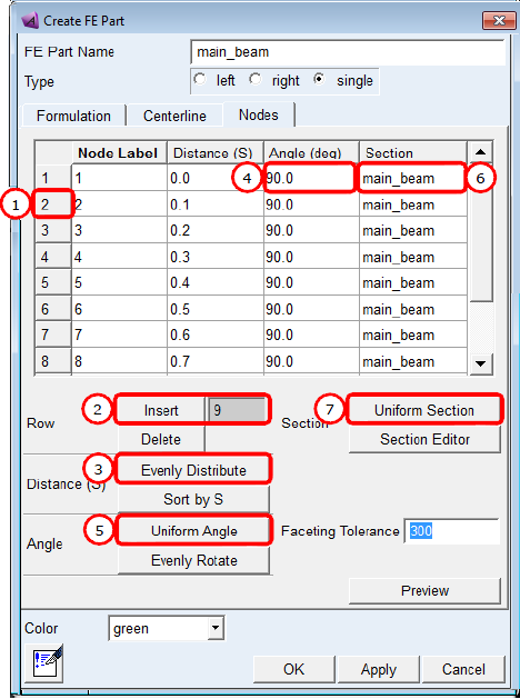
6. Click OK, and the FE part is created.
7. Select Build → Attachment → Joint → New and fill out the dialog box as follows:
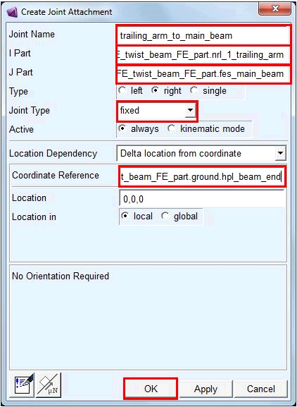
8. Click OK, and the joint is created on both the left and right sides
9. Save the template to your private database
At this point the model is functional. We will build a subsystem and assembly based on this template, then simulate the suspension system.
10. Switch back to the Standard Interface
11. Select File → New → Subsystem and fill out the dialog box as follows:
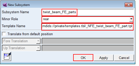
12. Click OK, and then Yes to use the template in memory to create the subsystem.
13. Select File → New → Suspension Assembly and fill out the dialog box as follows:
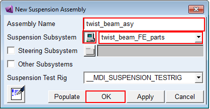
14. Click OK, and the assembly is created.
15. Select Simulate → Suspension Analysis → Opposite Wheel Travel and fill out the dialog box as follows:
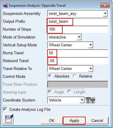
16. Click Apply and the analysis starts. Message window with loading analysis results will pop up. Click Close to acknowledge that message.
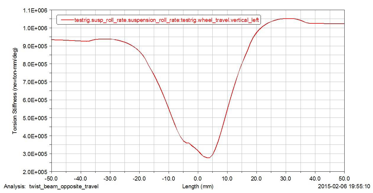
17. Once the analysis has completed, select Review → Post Processing Window
18. Plot quantities of interest to show that the analysis produced meaningful roll stiffness results.