Positioning the Flexible Link
Currently, the link is not positioned where it needs to be. There are four positioning tools available:
■Align Flex Body CM with CM of Current Part
■Launch Precision Move Panel
■3 Point Method
■Node ID Method
In this tutorial, you’ll use the first two.
To position the flexible link based on the center of mass (CM):
In the Swap a rigid body for flexible body dialog box, select the Align Flex Body CM with CM of Current Part button.
Adams Flex moves the link so the CM of the rigid and flexible links align.
Keep in mind that the finite element discretization of a solid will naturally have an inertia tensor and CM location that is slightly different than that of an analytical solid, due in large part to the facetization. Therefore, you may find that you need to make small precise adjustments to the position and/or orientation of the flexible body so it fits correctly into the rest of your model.
To position the flexible link precisely:
1. In the Swap a rigid body for flexible body dialog box, select the Launch Precision Move Panel button.
The Precision Move dialog box appears, as shown in the figure below. Notice that many of the text boxes have been automatically filled in with the position and orientation of the flexible body relative to the ground coordinate system.
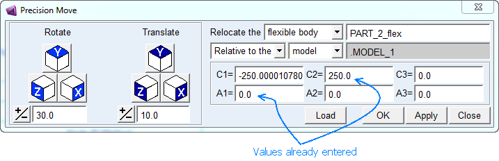
Figure 2 Precision Move Dialog Box
The C1, C2, and C3 text boxes display the location of the flexible body with much precision:
-250.0000107801, 250.0, 0.0
The A1, A2, and A3 text boxes display the angular orientation, and they appear acceptable:
0.0, 0.0, 0.0
2. Clear the C1 text box, and enter the value: -250.
3. Select OK.
The location of the link has now been corrected to a higher level of position.