Creating Poly-V Grooved Belt System
In this section, you will create a belt system.
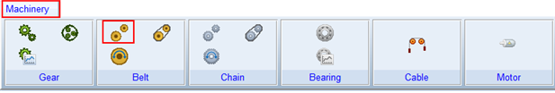
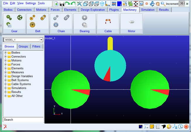
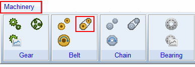
1. Click the Machinery tab on the Adams View ribbon.
2. From the Belt container, click the icon for Create Pulley.
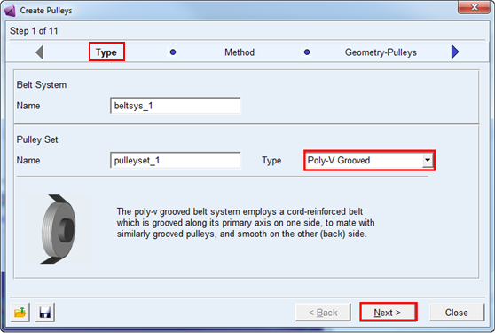
3. The pulley creation wizard will launch. On the first page (Type) select Poly-V Grooved from the Type option menu and click Next.
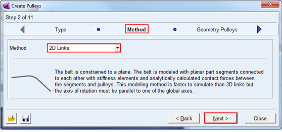
4. On the next page (Method) select 2D Links from the Method option menu and click Next.
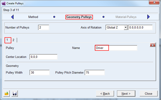
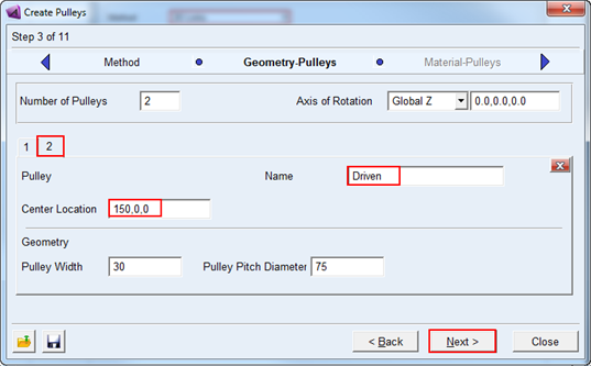
5. On the next page (Geometry) fill out the two tabs defining each pulley's geometry as shown below and then click Next:
a. Pulley1 name as Driver and Pulley2 name as Driven.
b. Pulley1 center location as 0,0,0 and Pulley2 center location as 150,0,0.
6. The next page (Material-Pulleys) defines the material properties to be used for the mass property calculations for each pulley. Accept the defaults and move on by clicking Next.
7. On the next page (Connection-Pulleys) you define how each pulley is to be connected to the rest of the model. For this example, accept the defaults which mount each pulley to ground via revolute joints and click Next.
8. On the next page (Output-Pulleys) you can optionally reduce the amount of post-processing information about the pulleys to be made available as Adams Requests. For this example, accept the defaults (to get all information) and click Next.
9. The next page (Completion-Pulleys) informs you that all the information required for the grooved pulleys has been entered. Click Next to proceed to tensioner definition.
10. On this page (Geometry - Tensioners) enter 1 in the Number of Tensioner with Deviation Pulley field and fill out the tabs defining the tensioner arm and deviation pulley geometry as shown below and then click Next:
11. The next page (Material-Tensioners) defines the material properties to be used for the mass property calculations for the tensioner arm and deviation pulley. Accept the defaults and move on by clicking Next.
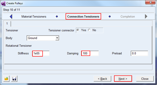
12. On the next page (Connection-Tensioners) you define how the tensioner arm is to be connected to the rest of the model. Since we selected a rotational type of tensioner earlier in the wizard, the tensioner arm will be mounted via a revolute joint and a rotational spring-damper will be applied to the remaining rotational degree of freedom. Here we define to which body in the model the tensioner arm is mounted and specify the spring damper coefficients.
13. The next page (Completion) informs you that all the information required for the pulley set has been entered. Optionally save the content of the entire wizard to a file for re-use later by clicking the Save icon. Click Finish to create the pulley set.
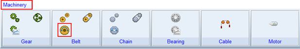
16. From the Ribbon go to the Machinery tab's Belt container and click the icon for Create Belt.
14. The Belt Creation wizard is launched. In the Name field enter the name of the pulley set you just created (right-mouse-click in the field and use Pick or Guesses to quickly select) and then click Next.
15. The next page (Method) defaults to the method you chose when creating the pulley set. Accept this default by clicking Next.
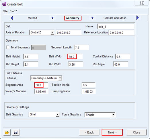
16. The next page (Geometry) is for specification of the Belt geometry. Make the modification as shown below and click Next to move on.
17. The next page (Mass) defines the material properties to be used for the mass property calculations for the belt segments. Accept the defaults and move on by clicking Next.
18. On the next page (Wrapping Order) the belt routing is defined. Right-click in the field and use the Guesses menu to first pick the Driver, then the roller and finally the Driven so that the field is populated as such: "pulleyset_1_Driver, pulleyset_1dev_roller, pulleyset_1_Driven", then click Next.
19. When prompted about the belt number of segments, tension and strain; click OK to continue. A warning message will be displayed informing you that the 2D parts for the belt segments are unique to the Adams Solver C++ executable (the default mode).
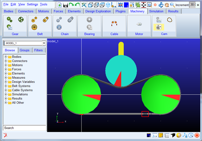
20. Now you will be on the Output Request page. Create a request of type Segment Request and populate the Link Part(s) field (for example, via right-click Pick) with a belt segment (57) near the bottom of the follower pulley. This will create output requests to track the forces on that segment as the belt runs around the pulleys. You may want to toggle the icon display off to better see the belt (one way to do this is to click inside the graphics window and press the "v" key on your keyboard). Click Next.
21. The next page (Completion) informs you that all the information required for the belt has been entered. Optionally save the content of the entire wizard to a file for re-use later by clicking the Save icon. Click Finish to create the belt.
22. From the Ribbon go to the Machinery tab's Belt container and click the icon for Belt Actuation Input.
23. The Actuate Belt wizard is launched. In the Pulley Set Name field enter the name of the pulley set you just created (right-mouse-click in the field and use Pick or Guesses to quickly select). In the Actuator Pulley field enter the name of the driver pulley (right-mouse-click in the field and use Pick or Guesses to quickly select). Then click Next.
24. On the next page (Type) select Motion and click Next.
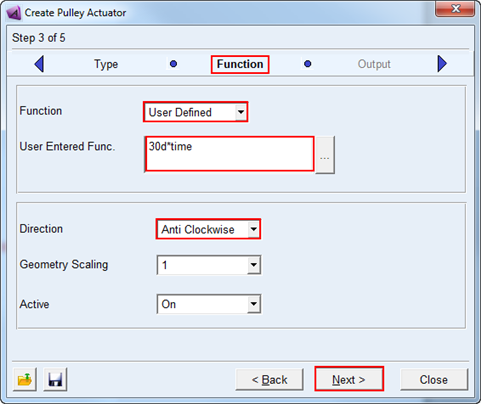
25. Complete the next page (Function) as shown below and click Next.
26. On the next page (Output) you can optionally reduce the amount of post-processing information about the actuator to be made available as Adams Requests. For this example, accept the defaults (to get all information) and click Next.
27. The next page (Completion) informs you that all the information required for the actuation has been entered. Optionally save the content of the entire wizard to a file for re-use later by clicking the Save icon. Click Finish to create the actuator.