Creating Rudder Module
In this section, you will create a rudder system for a light aircraft.
1. Copy rudder.cmd and rudder.xmt_txt from <topdir>\amachinery\examples\cable to your working directory
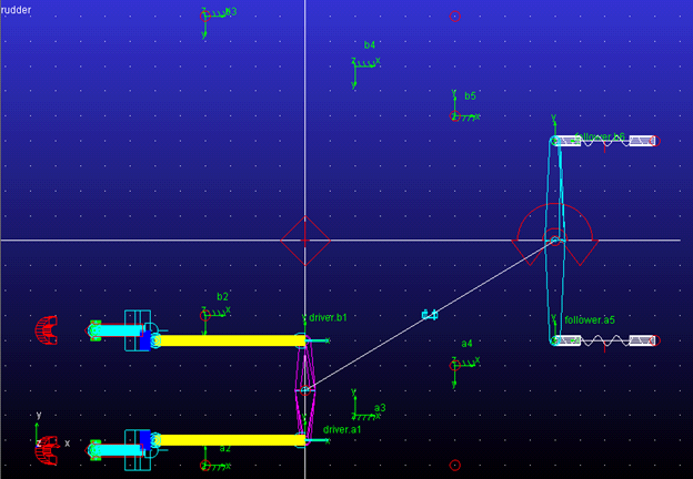
2. Open AView and import existing model rudder.cmd.
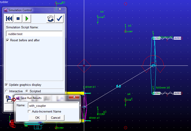
3. Run a scripted simulation using the simulation script test and save the analysis results as 'With_Coupler'.
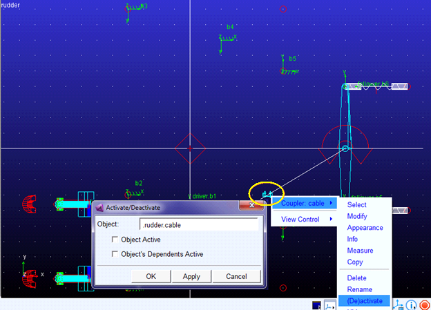
4. Return to Adams View and deactivate the coupler named cable by right clicking the coupler either from the model browser or from the graphics window, selecting (De)Activate and, from the ensuing dialog, un-checking both options.
5. Click the Machinery tab on the Adams View ribbon. From the Cable container, click the icon for Create Cable System.
6. In the Anchor Layout page, name the cable system and for Number of Anchors option enter 4 as the value.
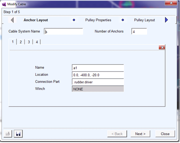
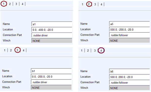
7. Specify the name, location and connection part for each of the four anchors as follows:
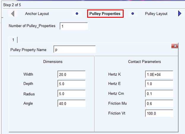
8. Click Next and proceed to create a pulley property set as shown below. The pulley property set is convenient way to store pulley cross-sectional dimensions and contact parameters which you can use for multiple pulleys in the cable system.
9. Click Next and proceed to create 7 pulleys a2, a3, a4, b2, b3, b4, and b5, respectively.
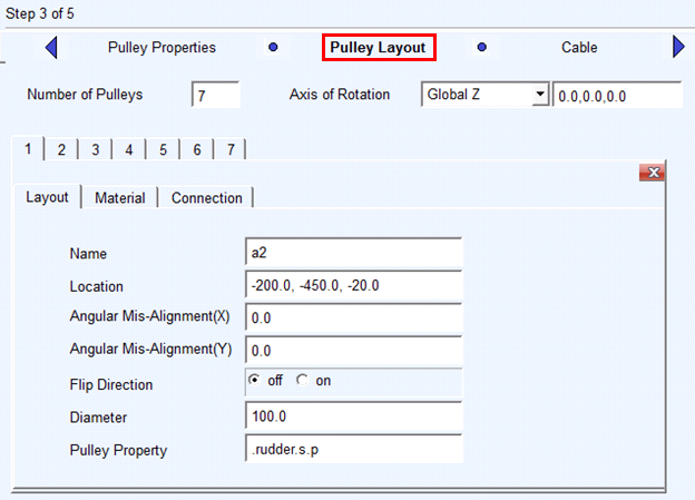
10. Fill in the properties for all pulleys as below. Enter correct flip direction.
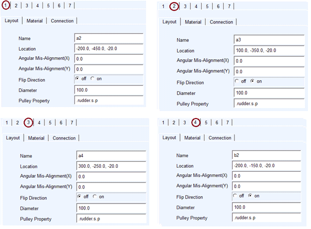
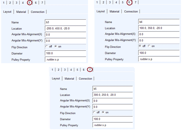
Connection part is ground with revolute joint for all pulleys.
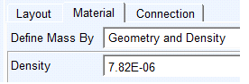
11. Materials Specification as below:
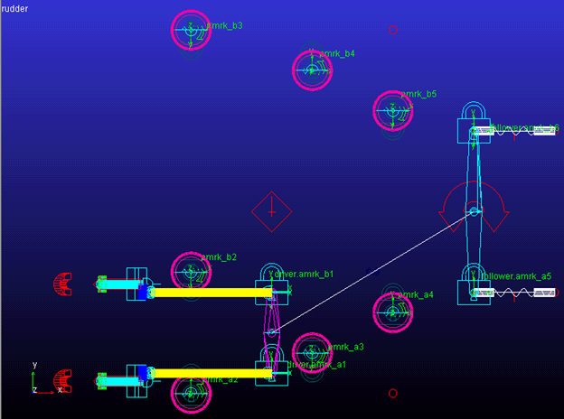
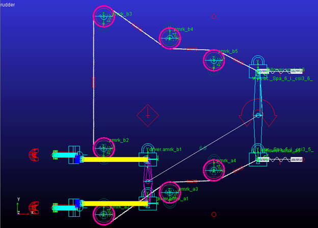
12. The pulleys will be visible as shown below:
13. Click Next and proceed to create 2 cables.
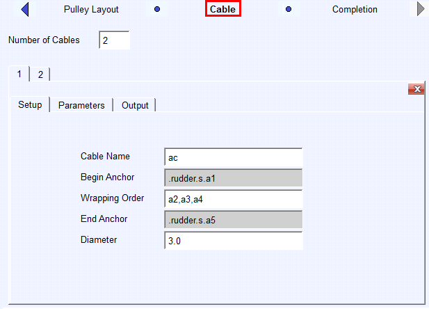
First cable specifications: 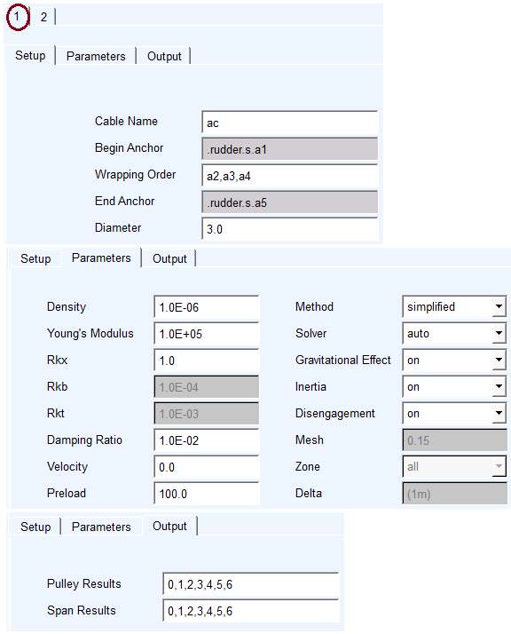
Second cable specifications: 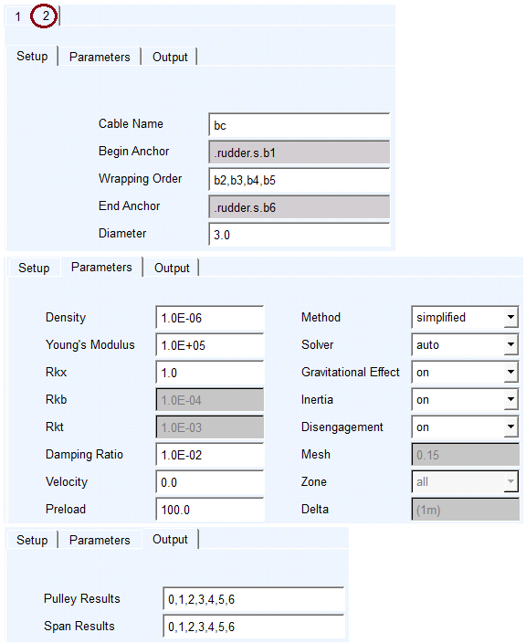
14. Click Next and the cables are created.
15. Click Finish to execute wizard.
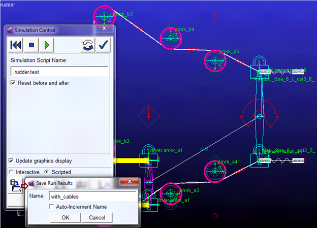
16. Now that a cable system is in place (replacing the simple coupler used initially), re-run the simulation using the simulation script test.
17. Save the analysis as with_cables.