Creating Nonlinear Flexible Body within Adams View
1. Copy the file "hmass_f_x.bdf" from "<top_dir>\flex\examples\maxflex\" to your working directory. For example, Windows examples files placed in the below location:
C:\Program Files\MSC.Software\Adams\2024_1\flex\examples\maxflex\hmass_f_x.bdf.
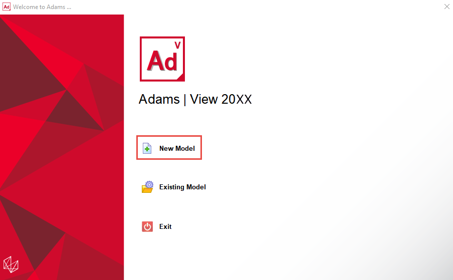
2. Start Adams View.
3. From the welcome screen click “New Model”.
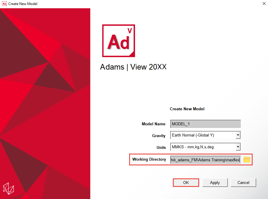
4. On the Create New Model dialog box set the Working Directory to the location where you placed the files for this example and click OK to proceed:
5. Click the Bodies tab. From the Flexible Bodies container click the Create a Flexible Body icon.
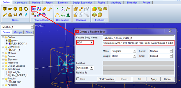
6. Choose the option “BDF” (Bulk Data File), double-click in the field and browse for the file “hmass_f_x.bdf” which was provided with this example (it should be in the working directory you selected when creating the model above). Then, click OK to import the BDF file and create the flexible body.
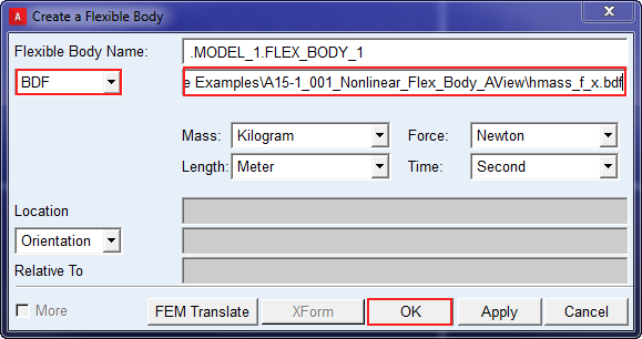
Notes: | ■When importing BDF files for flexible body creation, the units menus on this dialog should be set to match the units with which the BDF was created so Adams View can properly scale the flexible body to the Adams View model units. If the units are specified in the BDF then these menus are disabled and will reflect those units. If the units are not specified in the BDF, as in this example, then these menus are enabled. In this example, you can accept the default units here since they match what was set in the FE pre-processor when this BDF was created. ■Ignore any warning regarding incompatibility of the model with the FORTRAN flavor of Adams Solver that might appear. The C++ flavor of Adams Solver is the default and what will be used for this example. |
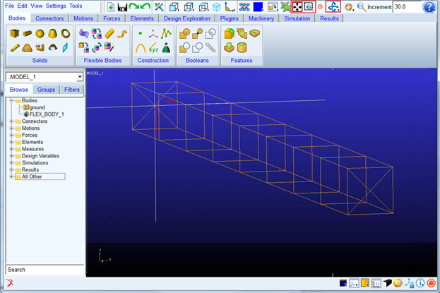
7. Rotate, fit and zoom the view to better examine the flexible body which was created:
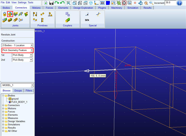
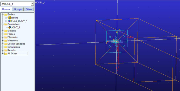
8. Create a revolute joint between the flexible body and ground, located at the model origin and oriented along the global X-axis:
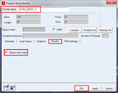
9. Right-click the flexible body (either in the graphics window or the model browser) and select Modify. Go to the Results tab and select Stress and Strain to request that these quantities be available for post-processing. Click OK to save these changes to the flexible body.
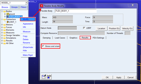
Note: | To learn about the other options on this dialog box see the dialog box help (accessible via pressing the F1 key while in this dialog box). |
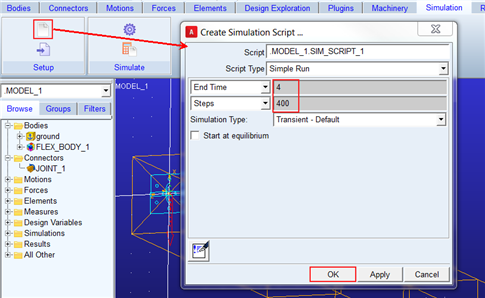
10. Create a simulation script for a 4-second, 400 step transient analysis as shown below:
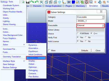
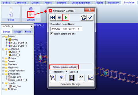
11. Adams models with nonlinear flexible bodies must be run by the external or standalone C++ Adams Solver executable. Internal Adams Solver jobs launched from Adams View are unsupported. So, specify use of the external Adams Solver executable as shown below:
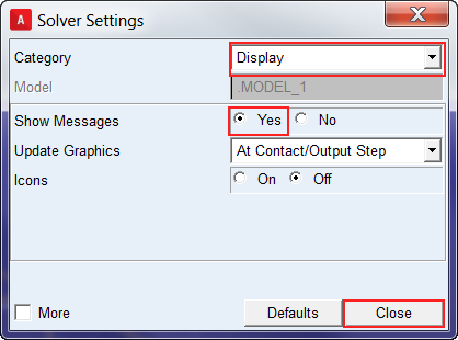
12. Also, request for messages to be displayed to within Adams View while external Adams Solver is running and close the dialog box:
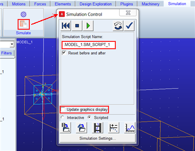
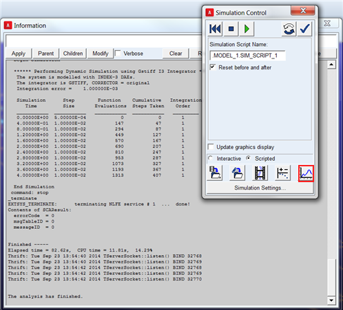
13. Run a scripted simulation on the single pendulum using the simulation script created earlier. To speed things up, keep the graphics display update off:
14. Once the analysis completes, open Adams PostProcessor.
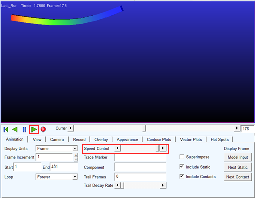
15. Right-click in the plot window and select “Load-Animation” to animate the analysis results. If it’s too fast, slow down the playback somewhat with the Speed Control slider.
16. Return to the Adams View window and open the flexible body creation dialog to create the second body of the double pendulum by importing the same BDF as you did for the first flexible body:
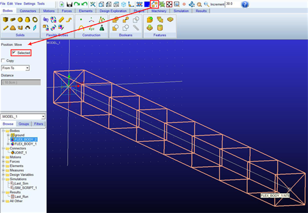
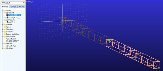
17. The second flexible body will be created in the same location as the first one. So, to move it, select it from the Model Browser, right-click the move stack and select the point-to-point move, check selected in the definition container, follow the status bar prompts and pick the global origin and then the end of the original flexible body:
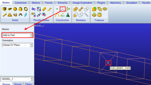
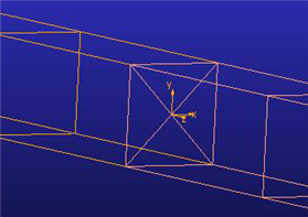
18. Create a marker on either flexible body at the midpoint of the intersecting faces oriented same as the global origin:
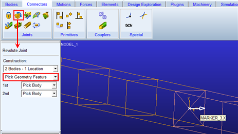
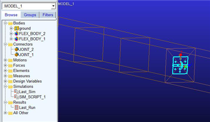
19. Connect the two flexible bodies with a revolute joint using the x-axis of the marker created in the previous step to orient it:
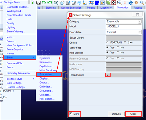
20. Set the Adams Solver thread count to 2. This will allow each flexible body to be solved in parallel on separate processors. To see this field you will need to check “More” on the Solver Settings – Executable dialog box:
21. Now with the double pendulum model, run an analysis using the same simulation script as before:
22. Same as was done for the first flexible body, right-click and modify the second flexible body so as to request the generation of stress and strain results:
23. Once the simulation completes, return to Adams PostProcessor and animate the results as before.