Running with SIMulation Workbench® (no hardware)
Note: | This tutorial assumes you are using the Third Party Tool - Adams interface in SIMulation Workbench (SimWB) version 2018.1-0. It is possible to use the Third Party Tool - FMU with this version or earlier version of SimWB. The user interface will be slightly different than what is shown in this tutorial. If you are using an earlier version of SimWB, a patch from Concurrent may be required. |
Note: | You will need a SimWB MSC Adams or FMU license from Concurrent to complete these next steps. 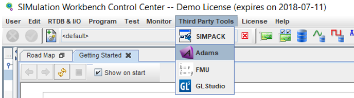 |
1. Launch SIMulation Workbench (Client) and import the Adams FMU model created in preceding step.
a. Select Third Party Tools > Adams menu
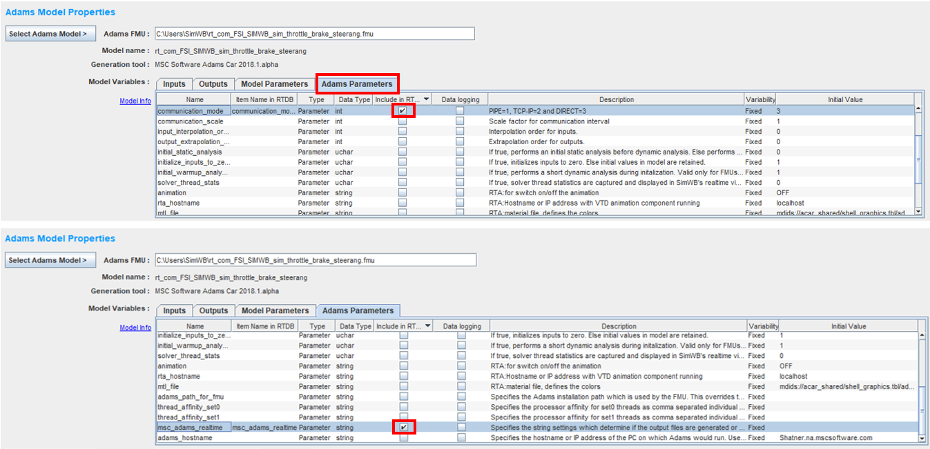
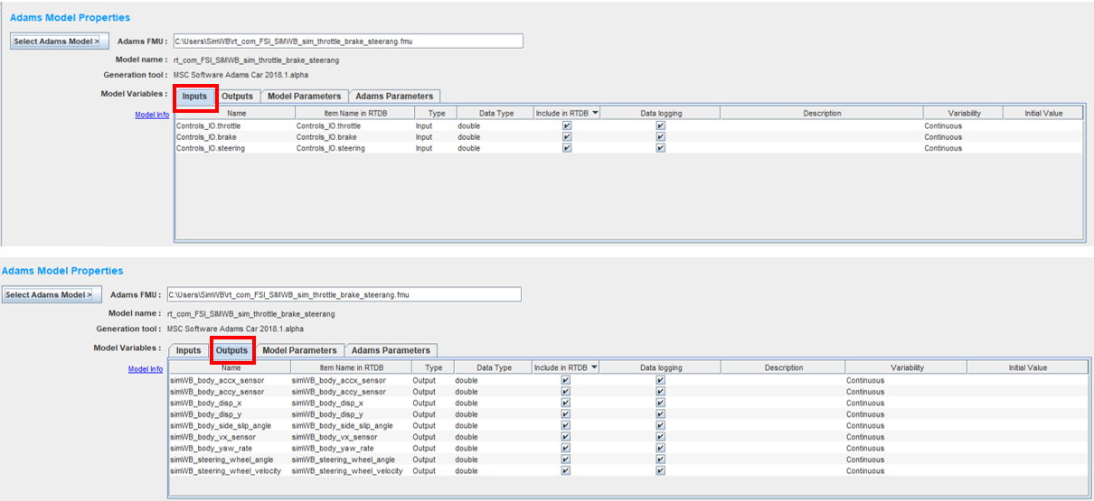
b. Click on Select Adams Model and right click in Adams FMU: to import "rt_com_FSI_SIMWB_sim_throttle_brake_steerang.fmu" to SimWB. The FMU is parsed and Model Variables: Inputs, Outputs, Model Parameters, and Adams Parameters are presented under a separate tab for inspecting the FMU file. Model Parameters are only listed if they were selected in the Adams Controls Plant Export during step 6 when exporting the FMU.
c. Click on Adams Parameters tab, locate communication_mode and check the Include in RTDB check box. Do the same for parameter msc_adams_realtime. Including these parameters in the RTDB makes it possible to change their initial values in a Test. Adams Parameters are variables that are fixed for the real time simulation. By default, they are not included in the RTDB. Their initial values can be modified if you check the box under the Include in RTDB column. Then you could use the Test - Initial Conditions menu to modify their initial value.
d. Check New RTDB and specify the name of the new real time database in Model RTDB: as shown below. Click on Generate RTDB. A RTDB is created in SimWB with the Model Parameters selected.
e. Select Install Adams Model to install the FMU file so it can be used in SimWB. And executable of the Adams FMU is created that can run in SimWB. Now you will be able to communicate with the Adams model in the FMU.
f. Click on  to save your changes.
to save your changes.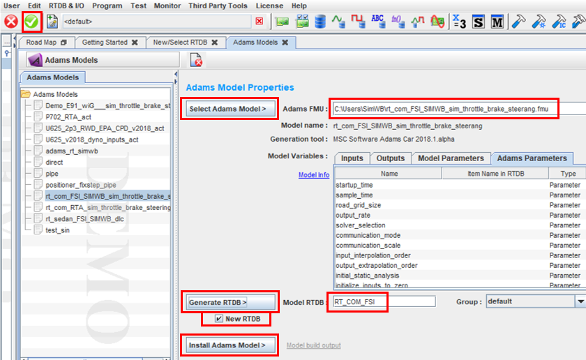
2. Select the Model Variables Inputs and Outputs tabs to review the inputs and outputs that were defined for the FMU. All inputs and outputs are automatically included in the RTDB so their continuous channel can be mapped to input/ouput devices. If they are not needed for a particular test configuration, you can uncheck their Include in RTDB box.
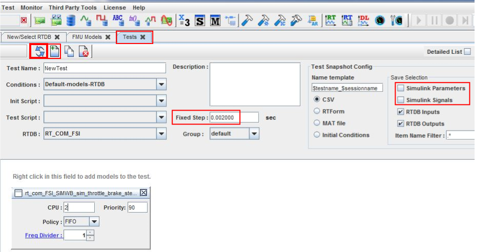
3. Select Test → Tests and click on  to refresh the new RTDB for a new test.
to refresh the new RTDB for a new test.a. Click on  to create a new test. Give it a name or take the default of NewTest.
to create a new test. Give it a name or take the default of NewTest.b. Right click in the white field and add "rt_com_FSI_SIMWB_sim_throttle_brake_steerangle.fmu" to the test under Adams Models.
c. Set Fixed Step: to 0.002 sec. (Depending on the clockspeed of your RT system, you may need to increase this number to prevent overruns)
d. Unselect Simulink Parameters and unselect Simulink Signals.
e. Click on .
.
4. Select Program → Environment Variables and click on to create a new environment file "FSI_SIMWB".
to create a new environment file "FSI_SIMWB".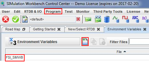
Click on and add the following environment variable(s), (if necessary) to run an Adams FMU in SIMulation Workbench:
and add the following environment variable(s), (if necessary) to run an Adams FMU in SIMulation Workbench:If the version number of Adams from which the FMU was created somehow differs from the version running in the SimWB environment, then set ADAMS_PATH_FOR_FMU to your Adams installation folder, for example, /msc/Adams/2024_1 (the path to your Adams installation). Otherwise, do NOT set this environment variable.
Click on to save changes to this file.
to save changes to this file.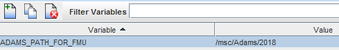
5. Select Test → Test Sessions and click on to create a new test session.
to create a new test session.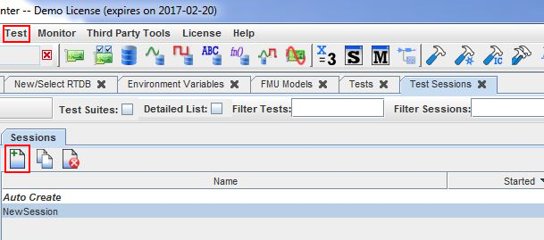
a. Logging is Enabled by default, but this can slow down the simulation, so if you don't need to log variables during the simulation, disable logging by unchecking the box  .
.
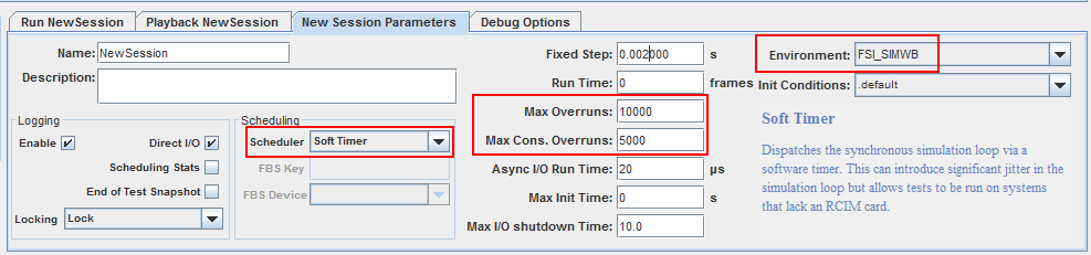
.b. Set Scheduler to Soft Timer unless you have an RCIM in hardware.
c. If necessary, set Environment to the FSI_SIMWB file containing the environment variables which was created in preceding step.
Change the Max overruns to 10000 and Max Cons. Overruns to 5000 to accommodate any overruns during initial transient conditions.
d. Click on to save your changes.
to save your changes.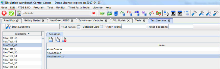
e. Click on the  button and verify that the simulation runs on SimWB. To see the execution time of the FMU, select Monitor → RT Viewer and click on Tab Scheduler Info as shown below. In this example, the execution time is 1.15ms (CPU: 2). Once you're done, click on the
  to stop the simulation.
button and verify that the simulation runs on SimWB. To see the execution time of the FMU, select Monitor → RT Viewer and click on Tab Scheduler Info as shown below. In this example, the execution time is 1.15ms (CPU: 2). Once you're done, click on the to stop the simulation.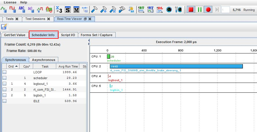
Notes: | When acar_solver.so is built with user subroutines, it needs to be placed at /tmp/acar_private/linux64 folder so that it is used instead of the standard acar_solver.so. |
If you see any initialization errors in the SimWB message window while starting the Adams FMU such as "AEI_Initialize: Error…" you may have to turn on Solver messaging which is off by default in DIRECT mode. There are two options for turning on messaging. One option is to set Adams Parameter msc_adams_realtime to MESSAGESON. This is done in the Test - Initial Conditions menu. Create a new one, in this case Default-models-RTDB and set the msc_adams_realtime variable which is an empty string to MESSAGESON. Next create a Test Session and specify Default-models-RTDB in the Init Conditions field. 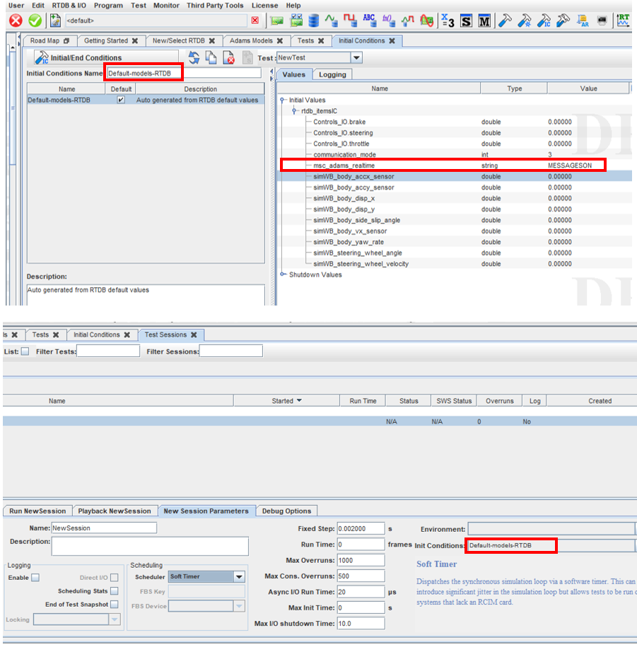 |
Notes: | Another option to turning on Solver messages is to switch from DIRECT to PIPE mode. This is done by changing the communication_mode from 3 (DIRECT) to 1 (PIPE) in Test - Initial Conditions. A standard Solver message file (.msg) in /tmp/fmi/resources directory will be created while executing the FMU in SimWB. It will slow down the simulation as a result, but it will allow you to examine the file for any error messages that will tell you what went wrong during model input phase. When PIPE option is being used and if the model has user subroutines, then an additional environment variable called HOME has to be defined and its value is to be set to "/tmp/". Follow the procedure defined in Step 4 to define this environment variable. |
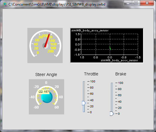
6. Select Monitor → HMI Builder to create a display to see the effect of throttle, brake and steering angle inputs.
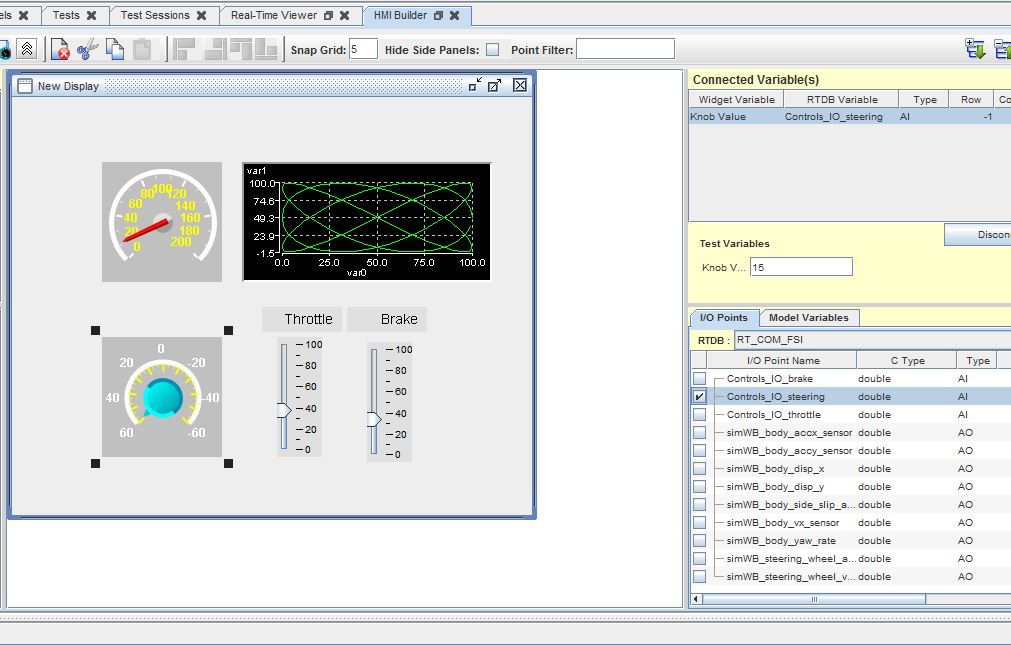
a. Click on to create a new display. Drag and drop the following widgets to the new display and connect them (verify that RTDB is set to RT_COM_FSI, see under Tab I/O Points in the figure below). An example of connecting the steering wheel angle to the Controls_IO_steering input is shown below.
to create a new display. Drag and drop the following widgets to the new display and connect them (verify that RTDB is set to RT_COM_FSI, see under Tab I/O Points in the figure below). An example of connecting the steering wheel angle to the Controls_IO_steering input is shown below.i. 2 Sliders, 1 for throttle (input Controls_IO_throttle 0-100%) and 1 for brake (input Controls_IO_brake 0-100%)
ii. 1 Knob for steering angle (input Controls_IO_steering in deg)
iii. 1 Gauge for representing forward velocity (output simWB_body_vx_sensor in km/h)
iv. 1 y Vs x Plot for representing the longitudinal (output simWB_body_accx_sensor in G) versus lateral acceleration (output simWB_body_accy_sensor in G).
Note: | Set the Format to %.1f to enable decimal values in G in the plot |
b. Click on  to save the display as "FSI_SIMWB_display.swbd".
to save the display as "FSI_SIMWB_display.swbd".c. Now the display pops up as shown below and you can start applying throttle, brake and steering inputs to the vehicle model as shown below.
d. Don't forget to click on the button to start the simulation and have fun driving the vehicle.
button to start the simulation and have fun driving the vehicle.