Adding a Spring
The spring between the hook and ground represents the clamping force when the hook engages the container. The spring should have a stiffness coefficient of 800 N/cm and a damping coefficient of 0.5 , so that a hook movement of 1.0 cm gives a large clamping force.
, so that a hook movement of 1.0 cm gives a large clamping force.As you create the spring, Adams View automatically creates markers to define the location and orientation of the spring. Because the hook vertex is not in the plane of the model, after you create the spring, you should modify the marker at the vertex so the spring is in the plane of the model.
To add a spring:
1. From the main menu, click the Dynamic Translate tool  to move your model to the right, to give yourself room to add the spring.
to move your model to the right, to give yourself room to add the spring. 2. Click the Forces tab on the Adams View ribbon.
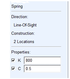
3. From the Flexible Connections container, click the Translational Spring-Damper tool  to create a spring between the ground and the hook.
to create a spring between the ground and the hook. 4. Set K to 800 and C to 0.5.
5. To add the spring, click at the following locations:
■Hook vertex, .HOOK.EXTRUSION_7.V16, near location (-14, 1, 0), making sure to select the vertex and not a point near it.
Tip: | To ensure that you select the hook vertex, right-click with the cursor near the vertex location (-14,1,0). A select list appears with all the vertices in the area. Select vertex 16. |
■(-23, 1, 0)
A red spring appears.
To modify a marker:
1. Right-click the location (-14, 1, 0).
A shortcut menu appears.
2. Point to Marker: MARKER_24, and then select Modify.
The Marker Modify dialog box appears.
Note: | The Marker name could be MARKER_26, if you have worked the tutorial from the beginning rather than starting from a cmd file. |
3. In the Location text box, change the location to (-14.0, 1.0, 0.0).
Adams View puts the spring in the plane of the model.
4. Select OK.
5. Use the View Fit tool  to fit your model to the screen.
to fit your model to the screen.