Wheel Envelope
Tools → Curve Manager
Generates a Wheel-Envelope Property File.
A wheel-envelope-input curve defines the boundaries of the vertical and steering travel used to compute a wheel envelope. During a wheel-envelope Analysis, Adams Car overlays the wheel-envelope-input curve with a grid and computes the position and orientation of the wheels at each point on the wheel-envelope curve.
The following table explains the default options that are common to both the plot and table Curve Manager views. For information on the options specific to each view, see Curve Manager Plot View or Curve Manager Table View.
For the option: | Do the following: |
|---|---|
Pull-down Menu | Select one of the following: ■Wheel Z vs Steer - For steerable suspensions, specifies wheel vertical positions (left and right) and steer travel. ■Left Z vs Right Z - For nonsteerable suspensions, specifies wheel vertical positions (left and right). |
Steering Input | Select one of the following: ■angle - The steering input is an angle applied to the steering wheel. ■length - The steering input is a length travel applied to the rack. |
Wheel: Interior | Enter a positive real number to fix the spacing of the wheel-center position points that Adams Car adds inside the curve before performing a wheel-envelope analysis. |
Wheel: Boundary | Enter a positive real number to fix the spacing of the wheel-center position points that Adams Car adds on the boundary of the curve before performing a wheel-envelope analysis. |
Steering: Interior | Enter a positive real number to fix the spacing of the steering input points that Adams Car adds inside the curve before performing a wheel-envelope analysis. |
Steering: Boundary | Enter a positive real number to fix the spacing of the steering input points that Adams Car adds on the boundary of the curve before performing a wheel-envelope analysis. |
Note: | The grid sizes and number of curve points determines the number of output points in the wheel-envelope analysis. Choosing small grid sizes increases the number of output points, which in turn increases solution times and output file sizes. |
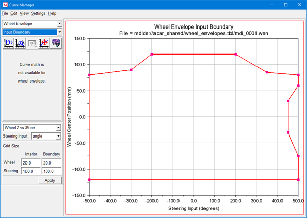
Below example shows wheel envelope input boundary for mdi_0001.wen file from acar_shared database.
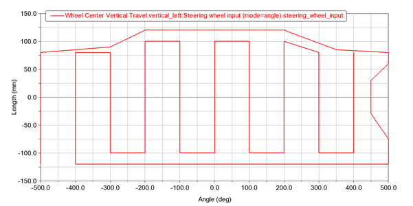
You will get below wheel traverse output plotted against steering wheel angle for above Wheel envelope input boundary. Wheel envelope analysis done on mdi_front_vehicle assembly from acar_shared database.
The Wheel path traverses the Wheel envelope boundary first, then zig-zags up and down the interior vertical grid lines (starting at the grid line with the minimum x value) with specified grid size in wheel envelope (*.wen) file.