Strut Modeling
Struts are specialized dampers designed to take bending and damping loads in the suspension. The same two damping definition options are available for a strut that are available for a shock. Struts are modeled with data stored in strut property files. Strut property files are stored in the dampers.tbl subdirectory of a vehicle database. The strut property files include three options for modeling the bending stiffness:
■Rigid (no bending)
Simple Bending Strut Model
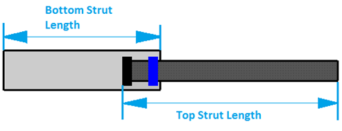
In the simple bending model, a bushing is attached to the upper strut piece, and is connected to the lower strut by a VFORCE statement. The VFORCE allows the reaction force on the lower strut to move with the upper strut. A second bushing moves with the lower strut, and is also modeled using a VFORCE statement
.
As the wheel moves into jounce, the two bushings get further apart, making the strut conically stiff to bending.
When the wheel moves into rebound, the two bushings coming together decreases the conical stiffness, therefore increasing the strut bending.
Complex Strut Model
The complex strut model in Adams includes structural compliance. The model contains 12 parts (six each left and right). The six parts are:
■Outer tube base
■Inner (pressure) tube base
■Piston
■Piston lash (dummy part)
■Rod guide
■Rod guide lash part (dummy part)
All the parts have negligible mass and the cg of the parts are as shown in following table:
Part | Mass and CM Location |
|---|---|
Lower Strut (attachment part) | Allocate aggregate mass of the strut lower assembly that is outer and inner tube. The CG to be calculated based on the dimension of outer and inner tube. |
Outer tube (BEAM, between lower strut and Rod Guide) | BEAM property calculated based on the dimension of the outer tube. This is modeled as a BEAM and does not have a mass. |
Inner (pressure) tube base | Negligible mass and CM at the lower attachment location. |
Piston | Negligible mass and CM at the distance equal to rod length from the upper attachment location. |
Piston lash | Negligible mass and CM located at the CM of the Piston. |
Rod guide | Negligible mass and CM at the distance equal to outer tube length from the lower attachment location. |
Rod guide lash part | Negligible mass and CM located at the CM of the Rod guide. |
Upper Strut (attachment part) | Allocate aggregate mass of the strut upper assembly that is piston and rod. The CG to be calculated based on the dimension of piston and rod. |
To provide the radial compliance of each part, the beam stiffness properties are programmed into a subroutine linked in to the Adams model. The radial compliance of the outer tube, inner tube, and piston are linked from the Adams data set to the subroutine code through several GFORCE statements. The axial stiffness of the strut is provided by an Adams BEAM statement that connects the inner tube base with the rod guide. The rod guide lash and piston lash are modeled as piecewise linear bushings, and the base cup is modeled as a linear bushing.
Property File Parameters | Explanation in the Diagram |
|---|---|
Rod Diameter | Rod Diameter |
Rod Length | Rod Length |
Rod Lash | Lash Distance Between Rod and Rod Guide |
Rod Stiffness | Stiffness Between Piston Rod and Rod Guide |
Inner Tube Outer Diameter | Inner Tube Outer Diameter |
Inner Tube Inner Diameter | Inner Tube Inner Diameter |
Inner Tube Length | Inner Tube Length |
Outer Tube Outer Diameter | Outer Tube Outer Diameter |
Outer Tube Inner Diameter | Outer Tube Inner Diameter |
Outer Tube Length | Outer Tube Length |
Piston Lash | Lash Distance Between Piston and Inner Tube |
Piston Stiffness | Stiffness Between Piston and Inner Tube |
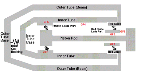
General Force | Acting part(s) |
|---|---|
GF1 | Attachment part (upper strut) and Rod Guide Lash |
GF2 | Rod Guide Lash |
GF3 | Rod Guide lash and Piston |
GF4 | Rod Guide and Piston Lash |
GF5 | Piston Lash |
GF6 | Piston Lash and Inner (pressure) Tube |