Load Case Data File Editor
The loadcases are specified via the Load Case Data File Editor and saved as an .xml file.
The Editor can be accessed directly from the Static Loadcase event in the Adams Car Standard Interface.
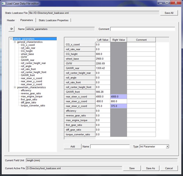
Parameters tab
You must supply vehicle parameters, such as GVW, GAWR front, GAWR rear, Cg Height, roll angle and powertrain parameters, such as gear ratio, efficiency, maximum engine torque. These parameters are used for calculating input loads to wheel.
See the following Parameters on the Load Case Data File Editor:
Static Loadcase Properties tab
The various load cases are specified under the Static Loadcase Properties tab.
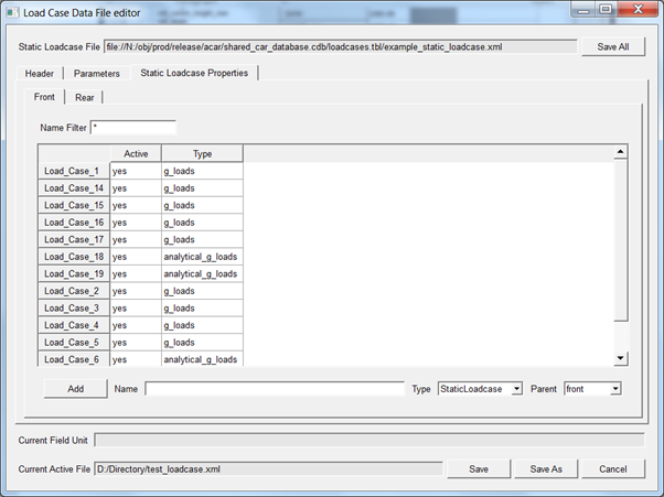
You can specify loadcases for the front and rear suspension in single loadcase file. Adams Car will only use data from Front tab for front suspension analysis and data from Rear tab for rear suspension analysis.
The "Active" column allows you to select which loadcases should be run for the current analysis. You can double-click on the load case of interest to modify the input data for that particular load case.
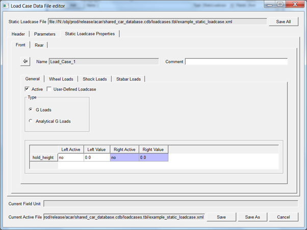
Static Loadcases
You can specify any number of loadcases. In the example loadcase file "example_static_loadcase.xml" available in the acar_shared database has few loadcases defined as an example.
Under "General" tab you can select loadcase type as below:
■G Loads
■Analytical G Loads
■Hold height:
Used to set initial/start position of suspension assembly.
■User Defined Loadcase:
If user defined loadcase is selected, location of forces acting at contact patch only changed to your specified location.
■You can specify your location by adding below parameters in parameters tab
For front suspension:
♦front_user_defined_x
♦front_user_defined_y
♦front_user_defined_z
For Rear Suspension:
♦rear_user_defined_x
♦rear_user_defined_y
♦rear_user_defined_z
G Loads
G loads type offer different options like wheel loads, shock loads and stabar loads
You can specify load magnitudes that are applied at certain locations. The load specifications should be in G's for forces and in Nmm for torques.
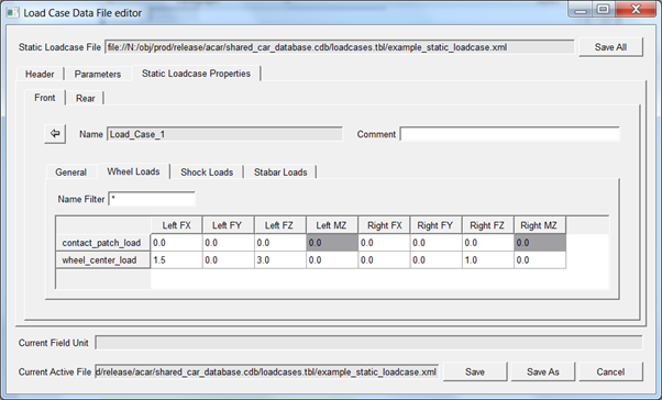
Wheel loads
Loads can be applied at the contact patch or wheel center. You can also apply loads at the contact patch in certain directions and at the wheel center in other directions.
All the applied loads are in G's. and one G value is based on GAWR for front (or GAWR for rear suspension) from parameters tab.
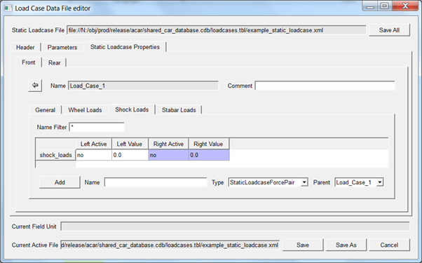
Shock loads:
If shock_loads are set to active, it applies force along the axial direction of shocks. Applied loads are in G's.
Note: | Currently only one pair of shocks are supported |
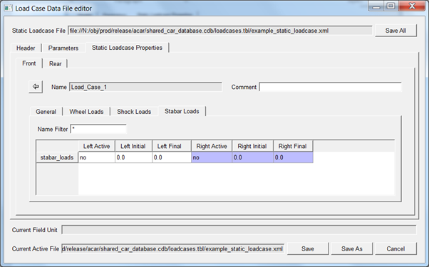
Stabar Loads
If stabar_loads are set to active, it applies motion to the wheel from initial value to final value and all forces (Wheel loads, shock loads) are set to zero.
This can be used to do motion based parallel wheel travel or opposite wheel travel.
Analytical G Loads
The following analytical loadcases are supported:
■Panic Braking
■Braking
■Cornering
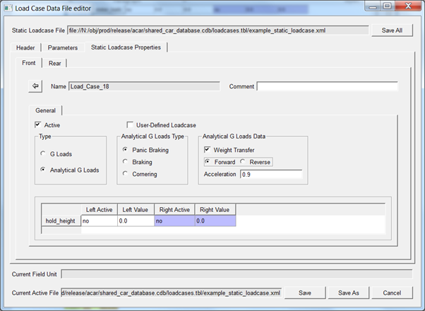
Panic Braking
Panic braking can be performed with and without weight transfer. The formulation used are as follows:
Forward braking long.accel = | +ve |
Reverse braking long.accel = | -ve |
With weight transfer | |
front suspension = Max fz = | (GAWR + GVW * long.accel * CG Height/Wheel Base)/GAWR |
rear suspension = Max fz = | (GAWR - GVW * long.accel * CG Height/Wheel Base)/GAWR |
Max fx = | accel * Max Fz |
Without weight transfer | |
Max fz = | 1.0 G |
Max fx = | accel |
Braking
Forward braking long.accel = | +ve |
Reverse braking long.accel = | -ve |
Front suspension = Max fz = | GVW/(2*Wheel base) * (L_to_CG + long.accel * CG Height) |
Rear suspension = Max fz = | GVW/(2*Wheel base) * (L_to_CG - long.accel * CG Height) |
Max fx = | mu * Max fz * sign(accel) |
Cornering
Left Turn Direction = | -ve weight transfer to the right (outside of turn) |
Right Turn Direction = | +ve weight transfer to the left (outside of turn) |
Lateral Load transfer = | ((front/rear)roll_rate * roll_angle + ((front/rear)GAWR * roll_center_height * lat.accel))/track_width |
Left Wheel Max fz = | max(sign(turn direction)*delta_load + (GAWR/2),0) |
Right Wheel Max fz = | max(-1.0 * sign(turn direction)*delta_load + (GAWR/2),0) |
Max fy = | mu * Max fz |