Attachments
When working with template-based products, you can use three types of attachments:
Joints
Joints define a rigid connection between two parts and help define the motion of the parts. The following table lists the joints the template-based products support, along with information about their degrees of freedom (DOF):
Joint name: | Number of DOF: | Type of motion DOFs allow: |
|---|---|---|
Translational | 1 | Translation of one part with respect to another while all axes are co-directed. |
Revolute | 1 | Rotation of one part with respect to another along a common axis. |
Cylindrical | 2 | Translation and rotation of one part with respect to another. |
Spherical | 3 | Three rotations of one part with respect to the other while keeping two points, one on each part, coincident. |
Planar | 3 | The x-y plane of one part slides with respect to another. |
Fixed | 0 | No motion of any part with respect to another. |
Inline | 4 | One translational and three rotational motions of one part with respect to another. |
Inplane | 5 | Two translational and three rotational motions of one part with respect to another. |
Orientation | 3 | Constrains the orientation of one part with respect to the orientation of another one, leaving the translational degrees of freedom free. |
Parallel_axes | 4 | Three translational and one rotational motions of one part with respect to another. |
Perpendicular | 5 | Three translational and two rotational motions of one part with respect to another. |
Convel | 2 | Two rotations of one part with respect to the other while remaining coincident and maintaining a constant velocity through the spin axes. |
Hooke/Universal | 2 | Two rotations of one part with respect to the other while remaining coincident. |
You can use different parametric orientation options to define the location and direction of the joint.
To create or modify a joint:
1. From the Build menu, point to Attachments, point to Joint, and then select New/Modify.
2. Press F1 and then follow the instructions in the dialog box help for Create/Modify Joint Attachment.
3. Select OK.
Working with Bushings
Bushings provide a six degree-of-freedom force relationship for connecting two components. The force is applied between a marker on each component. The force depends on the relative displacement and the relative velocity of the two markers.
The forces generated due to translational and rotational motion are entirely uncoupled from each other. In the description of the bushing formulation that follows, you can apply the force dependencies, described next, to either translational or rotational behavior. Therefore, a statement such as fi = h (relative displacements, relative velocities) implies the following:
■Forces: fi = g (translational displacements, translational velocities)
■Moments: fi = h (angular displacements, angular velocities)
Learn about bushings:
Creating and Modifying Bushings
When working in Template Builder, you can create bushings and then modify them. When working in Standard Interface, you can only modify and replace bushings. Learn about the Interface Modes. If you replace a nonlinear bushing with any other bushing definition, the new property file will be added to the bushing's property file list.
Nonlinear Bushings
To create a nonlinear bushing:
1. From the Build menu, point to Attachments, point to Bushing, and then select New.
2. Press F1 and then follow the instructions in the dialog box help for Create/Modify Bushing Attachment.
3. Select OK.
To modify a nonlinear bushing in the Template Builder:
1. To display the modify dialog box, do one of the following:
■From the Build menu, point to Attachments, point to Bushing, and then select Modify. To load the parameters for a specific bushing, you must specify the bushing you want to modify.
■Right-click a bushing, point to its name, and then select Modify. The dialog box has the bushing parameters already loaded.
2. Press F1 and then follow the instructions in the dialog box help for Create/Modify Bushing Attachment.
3. Select OK.
To modify a nonlinear bushing in the Standard Interface:
1. In Standard Interface, right-click a bushing, point to its name, and then select Modify. The dialog box has the bushing parameters already loaded.
3. Select OK.
Linear Bushings
To create a linear bushing:
1. In Standard Interface, right-click a bushing, point to its name, and then select Replace Instance.
2. Press F1 and then follow the instructions in the dialog box help for Replace Instance Definition.
3. Select OK.
To modify a linear bushing in the Standard Interface:
1. Right-click a bushing, point to its name, and then select Modify. The dialog box has the bushing parameters already loaded.
3. Select OK.
FMU Bushings
Any existing bushing can be replaced with a Functional Mock-up Interface (FMI) submodel. This allows the user to create a "closed box" bushing model. The user first creates the bushing model in a controls modeling package (for example, Easy5 and Matlab), and exports this model as an FMU. The FMU is assumed to be built with the following convention:
■Positive displacement & velocity mean the bushing is in tension.
■Positive displacement & velocity produce positive force.
■If users choose to author an FMU such that positive displacement & velocity produce negative force, they will need to set the force/torque scale factors to -1.
■Adams Car does not require any particular units convention in the FMU. Users are responsible to set the scale factors if the FMU was modeled in a different unit system than the Adams Car model.
Use of an FMU bushing requires a license of Adams Controls. Any number of bushings can be replaced with FMU bushings, but there will be some Solver performance degradation associated with each FMU bushing instance.
FMU Input/Output Signal Convention
Adams sends six displacement and six velocity states to the FMU, and expects six force components to be returned. These signals must be named according to the table below. All values are calculated in the bushing reference frame as defined by the J marker of the bushing. This is defined in the Adams Car template.
Type | Name | Description |
|---|---|---|
Input | Displacement_X | Relative Displacement in X direction of I part with respect to J part |
Input | Displacement_Y | Relative Displacement in Y direction of I part with respect to J part |
Input | Displacement_Z | Relative Displacement in Z direction of I part with respect to J part |
Input | DisplacementAngular_X | Relative Rotation about the X axis of I part with respect to J part |
Input | DisplacementAngular_Y | Relative Rotation about the Y axis of I part with respect to J part |
Input | DisplacementAngular_Z | Relative Rotation about the Z axis of I part with respect to J part |
Input | Velocity_X | Relative translational velocity in X direction of I part with respect to J part |
Input | Velocity_Y | Relative translational velocity in Y direction of I part with respect to J part |
Input | Velocity_Z | Relative translational velocity in Z direction of I part with respect to J part |
Input | VelocityAngular_X | Relative angular velocity about X axis of I part with respect to J part |
Input | VelocityAngular_Y | Relative angular velocity about Y axis of I part with respect to J part |
Input | VelocityAngular_Z | Relative angular velocity about Z axis of I part with respect to J part |
Output | Force_X | Force acting on I part in X direction |
Output | Force_Y | Force acting on I part in Y direction |
Output | Force_Z | Force acting on I part in Z direction |
Output | Torque_X | Torque acting on I part about X axis |
Output | Torque_Y | Torque acting on I part about Y axis |
Output | Torque_Z | Torque acting on I part about Z axis |
The resulting force formulation for the FMU bushing is as follows:
FX = t_preload_x + fx_scaling_factor × (-1 × FMU output 1)
FY = t_preload_y + fy_scaling_factor × (-1 × FMU output 2)
FZ = t_preload_z + fz_scaling_factor × (-1 × FMU output 3)
TX = r_preload_x + tx_scaling_factor × (-1 × FMU output 4)
TY = r_preload_y + ty_scaling_factor × (-1 × FMU output 5)
TZ = r_preload_z + tz_scaling_factor × (-1 × FMU output 6)
Note: | A positive force acts to repel the I and J parts, resisting compression. |
To create an FMU bushing:
1. In Standard Interface, right-click a bushing, point to its name, and then select Replace Instance.
2. Press F1 and then follow the instructions in the dialog box help for Replace Instance Definition.
3. Select OK.
To modify an FMU bushing in the Standard Interface:
1. Right-click a bushing, point to its name, and then select Modify. The dialog box has the bushing parameters already loaded.
3. Select OK.
Bushings in Series
The bushings in series option allows you to model up to three bushings in a series without modeling the parts between them. The intent is to aid design studies by representing local part compliance as a bushing. Currently, only linear bushings can be used to model the I part and J part compliances, whereas the nominal bushing can use any of the available stiffness/damping formulations.
To use bushings-in-series in the Standard Interface:
1. Right-click a bushing, point to its name, and then select Modify. The dialog box has the bushing parameters already loaded.
2. Select the I Part Compliance tab. Switch the I part compliance toggle on. Supply a valid linear bushing property file.
3. Optionally you may now select the J Part Compliance tab and switch on its toggle.
5. Select OK.
Bushing Installation Angle
An initial bushing angle can be calculated for certain front and rear suspension bushings. This angle is calculated based on the pvs_wheel_center_rise parameter. The pvs_wheel_center_rise parameter must be present in the Parameters block in the subsystem file. For bushings where it is obvious how the vertical motion of the wheel will create a torque on a bushing, the effective lever arm for that bushing with the wheel center rise are used to calculate the angle. This angle represents the preload generated during assembly line installation of a suspension. The wheel center rise sign convention is negative for rebound.
Example Bushing Installation Angle Calculation for Double Wishbone Suspension
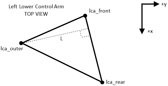
To calculate the bushing installation angle required for a given wheel rise (r), the effective arm length (L) is calculated.
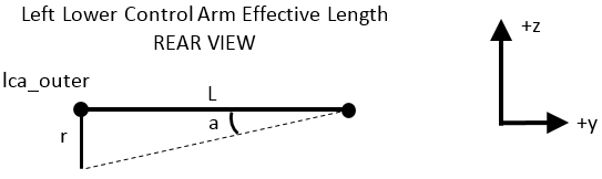
The installation angle is calculated by taking the arctan of r/L.
The bushing installation angle feature is available for the following suspension templates in the acar_concept database:
_central_link.tpl
_double_wishbone_advanced.tpl
_integral_link.tpl
_macpherson_advanced.tpl
_semi_trailing_arm_advanced.tpl
_trailing_arm_advanced.tpl
_twin_I_beam.tpl
_twist_beam_advanced.tpl
The following table shows which bushing models are supported in the installation angle calculation:
Product | Bushing model | Installation angle support |
|---|---|---|
Car | ac_bushing | Yes |
Car | ac_linear_bushing | No |
Driveline | ac_f_d_bushing | Yes |
Ride | ac_frequency_bushing | Yes |
Ride | ac_general_bushing | No |
Ride | ac_general_f_d_element | No |
Ride | ac_hydro_bushing | Yes |
Note: | The installation angle calculated due to wheel center rise will be overwritten, if Z angle offset is specified in the subsystem. |
About Bushing Property Files
The standard non-linear bushing component supports the following types of property files:
■TeimOrbit (TeimOrbit File Format) bushing property files (extension .bus) - Standard TeimOrbit bushing property files correspond to nonlinear stiffness forces with linear damping.
■XML (XML File Format) bushing property file - The XML bushing property file enables data sharing with other MSC Software applications, and allows greater flexibility and a wider range of bushing formulation choices. In particular, the XML bushing property file supports various methods and options for the calculation of force characteristics, as explained in Calculation of Force Characteristics. You work with XML files in the Property File Editor.
Adams supports markers that follow the right-hand rule only. This means a bushing on the left side of the vehicle cannot be truly mirrored to the right side. Two axes may be parallel, but one will always be pointed in the opposite direction. For a bushing with asymmetric stiffness curves for all three axes, this presents a problem.
In a TeimOrbit bushing property file (*.bus), you can insert a BUSHING_DATA section with a BUSHING_TYPE property, as follows:
$-------------------------------------------------------------------BUSHING_DATA
[BUSHING_DATA]
BUSHING_TYPE = 'left'
For XML bushing property file (*.xml), you can insert a "stiffness_curve" property within the "ConnectorBushingProperties" tag, as follows:
<ConnectorBushingProperties active="true" userDefined="false" shape="cylindrical" stiffness_curve="left" radius="20" height="40">
In either case, this triggers special processing in the bushing property reader. To take advantage of this feature:
1. Make sure the bushing orientation defined in the template matches your desired setup. Left and right X and Z axes must be parallel. Y axes should be opposite.
2. Build a bushing property file with the lines above, with the non-symmetric curves representing the left bushing.
3. In the subsystem, specify the new "left" bushing property file, and select "Symmetry=yes" so the same file is used on both sides.
4. When the property file is read, the right side FY, TX, and TZ curves will automatically be flipped.
Stiffness Forces Computation
The standard non-linear bushing force calculations are outlined below. In the expressions that follow:
■i, j k, l are indices whose integer values of 1 to 3 indicate application to the x, y, and z coordinate directions, respectively
■All uppercase letters represent constants
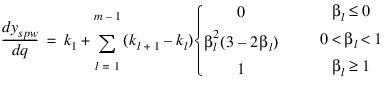
The Transformed Displacement, q
Adams Solver computes the stiffness forces based on a bushing displacement vector, q, which is determined by transformation to account for any inter-axial coupling. Therefore:
For uncoupled directions  , q is given by:
, q is given by:
For coupled directions  , q is given by:
, q is given by: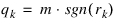
with 
and 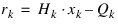
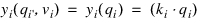
where the Adams internal variables are:
xk | - Displacement of the modeled bushing in the k direction |
rk | - Displacement of the physical bushing in the k direction |
qk | - Ordinate (lookup point) in the stiffness force characteristic |
D | - Scalar magnitude of the bushing displacement vector |
and the user-specified constants are:
Hk | - Horizontal (displacement) scaling for the kth direction (disp_scale); can be used to perform unit conversions |
Qk | - Displacement offset for the kth direction (disp_offset);can be used to specify an offset between the modeled bushing and the physical bushing (perhaps caused by the rotational preload introduced by the assembly process) |
This formulation allows the elements of the displacement vector, x, to be scaled up by a user-specified factor, H, and/or offset by a user-specified displacement offset, Qk, to determine the transformed displacement vector, qk, which becomes the lookup point in the selected stiffness force characteristic (see next).
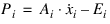
The Stiffness Force, f
For uncoupled directions  , the resulting force, f, is given by:
, the resulting force, f, is given by: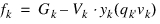
For coupled directions  , f, is given by:
, f, is given by: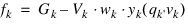
with  .
.
.Where the Adams internal variables are:
fk | - Stiffness component of the force in the kth direction, determined by accounting for preload, scaling factors, and inter-axial coupling |
yk | - Force returned internally by the user-defined (positive-positive) bushing stiffness characteristic for the kthdirection |
wk | - Weighting of the returned force for the kth direction (0 to 1, for coupled directions only) |
and the user-specified constants are:
Gk | - Force offset (preload) for the kth direction (force_offset) |
Vk | - Vertical (force) scaling for the kth direction (stiffness_force_scale) |
See the following sections for the precise mathematical descriptions of the two alternative coupling formulations.
Note about the scaling factors, V and H:
Notes: | Regardless of the bushing formulation, a doubling of the scale factor, V, results in a doubling of the restoring force provided by the bushing for a given displacement in that direction. In contrast, doubling of H: ■Results in a doubling of the restoring force for bushings whose force-displacement characteristics are linear. ■Results in a nonlinear change of the restoring force for bushings whose force-displacement characteristics are nonlinear. |
Expressing the Stiffness Force Characteristic
You can use a number of formulations to express the stiffness force characteristic of the bushing, by appropriately setting the integer value of stiffness_type (see above), and providing the necessary data in the .adm file.
Learn how the Stiffness Force Characteristics are expressed in the .adm file.
Linear
The linear characteristic is straightforward, and is defined using a stiffness, k:
Piecewise Linear
The piecewise linear characteristic is defined as:
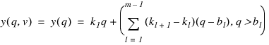
where:
qi | - The i-direction component of the (transformed) bushing displacement |
 | - The lth stiffness for the ith direction |
 | - The breakpoint where the stiffness changes between  and and  |
m | - The number of straight-line slopes that describe the characteristic |
Note that  is a necessary condition for all n.
is a necessary condition for all n.A typical characteristic from this formulation looks similar to the following:
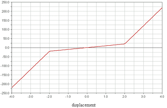
Figure 1 Example Piecewise Linear Force-Displacement Characteristic
Smoothed Piecewise Linear
The smoothed piecewise linear definition is similar to the piecewise, but with smoothing across each change in slope, such that the gradient of the force-displacement curve (for example, the stiffness) becomes continuous:
with:
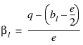
where (noting that for clarity, the subscript i, indicating direction, has been dropped):
q | - The (transformed, scaled and offset) bushing displacement |
kl | - The lth stiffness |
bl | - The breakpoint (value of displacement) where the stiffness changes between  and and  |
e | - The displacement over which each change in stiffness is smoothed to prevent discontinuities in stiffness |
m | - The number of straight-line slopes that describe the underlying characteristic |
This gradient is integrated analytically from zero displacement q, to find the force-displacement curve. The constant of integration is set such that if there were no smoothing, the curve would pass through the origin. As smoothing is introduced, this constant of integration (the vertical offset of the force-displacement curve) is adjusted such that the smoothed curve continues to overlay the unsmoothed curve in regions where there is no smoothing (such as those for high values of displacement). Note that this means that if the origin is contained within a smoothing interval, then the smoothed force-displacement curve may not pass exactly through the origin, but that you can safely vary the smoothing interval, knowing that as the displacement moves from a smoothed into an unsmoothed region, the behavior will converge to that of the unsmoothed piecewise curve.
Note that as with the piecewise formulation,  is a necessary condition for all n. Setting e to zero collapses this formulation to the piecewise formulation.
is a necessary condition for all n. Setting e to zero collapses this formulation to the piecewise formulation.A typical characteristic from this formulation will look similar to the following (where the plot shows the effect of varying the smoothing interval from 0.3 mm to 10 mm):
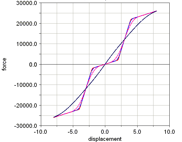
Figure 2 Example Force-Displacement Characteristic for a Smoothed Piecewise Linear Bushing
AKIMA Spline
The nonlinear, AKIMA spline characteristic is defined using a single Adams AKIMA spline. The restoring force is than determined directly from this spline:

Hysteretic (Dual-Spline)
The hysteretic definition of the stiffness characteristic also incorporates some damping (velocity-dependence) of the force, according to the following:
where:
with:
where:
Ai | - Horizontal (velocity) scaling for the ith direction (vel_scale) |
Ei | - Velocity offset for the ith direction (vel_offset) |
Pi | - Velocity saturation point (m/s) for the i direction (for hysteretic bushings only) |
pi | - Scaled and offset velocity in the i direction |
 | - Velocity (rate of change of model bushing displacement) in the i direction |
vi | - Transformed, and saturated  |
Such that, for v < -v, the force_neg_vel_values only are used, and for v > vel_threshold, only the force_pos_vel_values are used. When v is between these values, the two force characteristics are interpolated according to the STEP function described above.
Note that for very large values of P, the hysteresis disappears, and the characteristic approaches a simple displacement-dependent AKIMA spline:

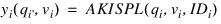
The following is an example of the typical behavior of a hysteretic bushing, excited to increasing amplitude:
Damping Forces Computation
Adams Solver computes the damping forces based on a transformed (scaled, and offset) bushing velocity vector, p, defined as:
where the Adams internal variables are:
 | - Rate of change of the true bushing displacement, x |
Pi | - Scaled and offset bushing velocity (the point in the force lookup) |
and the user-specified constants are:
Ai | - Horizontal (velocity) scaling for the ith direction (vel_scale) |
Ei | - Velocity offset for the ith direction (vel_offset) |
This formulation allows the elements of the true velocity vector,  , to be scaled up by a user-specified factor H, and/or offset by a user-specified displacement d, to determine the transformed displacement vector q, which is used as the lookup point in the definition of the stiffness force characteristic for the bushing.
, to be scaled up by a user-specified factor H, and/or offset by a user-specified displacement d, to determine the transformed displacement vector q, which is used as the lookup point in the definition of the stiffness force characteristic for the bushing.For each direction, the damping force, c is given by:
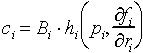
where the user-specified constant:
Bi - Is the vertical (force) scaling for the ith direction (damping_force_scale)
Expressing the Damping Force Characteristic
You can use several methods to specify the damping properties in each coordinate direction, as explained next.
None
This option simply deactivates damping for the given coordinate direction:
Linear
The linear characteristic is straightforward, and is defined using a damping constant, c:
For a linear characteristic, the parameter damping_value should be set equal to the required stiffness, c.
AKIMA Spline
The nonlinear, AKIMA spline characteristic is defined using a single Adams AKIMA spline. The damping-force characteristic is then determined directly from this spline:
Piecewise Linear
The piecewise linear characteristic is defined as:
where:
qi | - The i-direction component of the (transformed) bushing displacement |
 | - The lth stiffness for the ith direction |
 | - Breakpoint where the stiffness changes between  and and |
Note that  is a necessary condition for all n.
is a necessary condition for all n.A typical characteristic from this formulation will look similar to the following:
Figure 3 Example Piecewise Linear Force-Velocity Characteristic
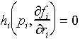
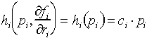
Stiffness Fraction ("k-fraction")
The stiffness fraction damping method simply ensures that the damping coefficient increases in proportion to the local stiffness of the bushing at the current operating point.
The damping force in each direction is determined by first identifying the local stiffness as being the modulus of the rate of change of the stiffness force in that direction with respect to a displacement in the same direction. This stiffness magnitude is then multiplied by the k-fraction, k, (damping_value) and multiplied by the appropriate component of the transformed velocity, p:
For an uncoupled linear bushing (D = 0 or 1, stiffness_type = 1), this reduces to a constant damping coefficient and a typical viscous damping characteristic.
Bushing Specifications in the Adams Dataset (.adm)
The standard non-linear bushings are implemented using a FIE(ld)SUB. This FIESUB reads the bushing specifications directly from the .adm deck, and returns the total (stiffness plus damping) force, fi + ci, for any six-element bushing displacement and six-element bushing velocity vector.
Coupling Specification
The value of D for the bushing is specified directly as shape in the FIELD statement for the bushing:
FIELD/id, I=idi, J=idj, FUNCTION=USER(branch, shape, txa, tya, tza, rxa, rya, rza)
where the value of the integer shape may be:
0 | - Rectangular (no coupling). The force in each direction is dependent only on the displacement in that direction. |
2 | - Cylindrical (that is, x-y coupling). The forces in the x and y directions are each dependent on the displacement of the bushing in both the x and y directions. The force in the z direction is independent (that is, it depends only on the displacement in z). |
3 | - Spherical (that is, x-y-z coupling). The force in each direction depends on the displacements in all translational directions, and the torque in each direction depends on the angular displacements in all rotational directions. |
Note that the selected shape factor (coupling) always applies to both the translational and rotational behavior of the bushing.
The next six parameters in the FIELD statement, all of which are required, should contain the Adams array IDs of the arrays containing the data, which expresses the stiffness and damping characteristic for the direction:
FIELD/id, I=idi, J=idj, FUNCTION=USER(branch, shape, txa, tya, tza, rxa, rya, rza)
Each of the referenced arrays must be included in the .adm file, and should be in the following form:
ARRAY/id, NUM= | stiffness_type, stiffness_value, stiffness_force_scale, … |
damping_type, damping_value, damping_force_scale, … | |
force_offset, disp_offset, disp_scale, vel_offset, vel_scale |
All of those parameters are required, and are described in detail in the following sections.
Stiffness Force Characteristic
You can use a number of formulations to express the stiffness force characteristic of the bushing, by appropriately setting the integer value of stiffness_type (see above), and providing the necessary data in the .adm file.
Linear (stiffness_type = 1)
For a linear characteristic, the parameter stiffness_value should be set equal to the required stiffness, k.
AKIMA Spline (stiffness_type = 2)
The nonlinear, AKIMA spline characteristic is defined using a single Adams AKIMA spline, specified by setting stiffness_value equal to the Adams ID of the spline. That spline must be supplied in the dataset, but can be shared among several directions and/or bushings.
Hysteretic Dual-Spline (stiffness_type = 3)
To specify this stiffness characteristic, the .adm file must include both a two-element array (whose integer ID is placed in stiffness_value), of the form:
ARRAY/id, NUM = sid, P
where the terms are defined as:
sid | - The Adams ID of the 3D spline that specifies the hysteretic characteristic |
P | - The (positive) velocity threshold above which the bushing characteristic becomes independent of the velocity |
and the associated Adams spline, of the form:
SPLINE/sid,
,X= [displacement_values]
,Y= -1.0, [force_neg_vel_values]
,Y= 1.0, [force_pos_vel_values]
Piecewise Linear (stiffness_type = 4)
When you select this stiffness type, you must provide an additional array in the .adm file, and you must set the value of stiffness_value (see above) equal to the integer Adams ID of that additional array. That additional array must be of the form:
ARRAY/id, NUMBERS = n, k(0), b(1), k(1), ... , b(n), k(n)
where:
n | - The number of slopes that define the stiffness characteristic. This number must be an integer and greater than 1 (note that for bushings with a single slope defining the stiffness characteristic, the linear stiffness type, stiffness_type = 1, should be used) |
b(1) ... b(n) | - The breakpoints. The values of displacement, or of angular displacement, at which the slope changes. These values must be real and in ascending order, but may be negative. |
b(m) | - The breakpoint where the slope (stiffness) changes from k(m-1), for displacements lower than b(m), and to k(m) for displacements greater than b(m). |
k(0) ... k(n) | - The slopes, all of which must be real and positive for a physical, passive bushing. Their units are stiffness (force/displacement) or angular stiffness (torque/angular displacement). Note that k(0) extends to minus infinity and k(n) to plus infinity. |
Note that the set k(0), b(1), k(1), ... , b(n), k(n) must contain precisely 2n-1 values, so that the total number of elements in the array must be 2n.
Smoothed Piecewise Linear (stiffness_type = 5)
When you select this stiffness type, you must provide an additional array in the .adm file, and you must set the value of stiffness_value (see above) equal to the integer Adams ID of this new array. For the smoother piecewise characteristic, the new array must be of the form:
ARRAY/ID, NUMBERS = s, n, k(0), b(1), k(1), ... , b(n), k(n)
where:
s | - The interval over which changes of slope are smoothed. This number must be a real value greater than zero, in units of displacement. |
n | - The number of slopes that define the stiffness characteristic. This number must be an integer and greater than 1 (note that for bushings with a single slope defining the stiffness characteristic, the linear stiffness type, stiffness_type = 1, should be used). |
b(1) ... b(n) | - The breakpoints. The values of displacement, or of angular displacement, at which the slope changes. These values must be real and in ascending order, but may be negative. |
b(m) | - The breakpoint where the slope (stiffness) changes from k(m-1), for displacements lower than b(m), and to k(m) for displacements greater than b(m). |
k(0) ... k(n) | - The slopes, all of which must be real and positive for a physical, passive bushing. Their units are stiffness (force/displacement) or angular stiffness (torque/angular displacement). Note that k(0) extends to minus infinity and k(n) to plus infinity. |
Note that the set k(0), b(1), k(1), ... , b(n), k(n) must contain precisely 2n-1 values, so that the total number of elements in the array must be 2n+1.
Damping Force Characteristic
For the stiffness characteristic, a number of methods exist for specifying the damping properties in each coordinate direction:
None (damping_type = 0)
This setting of damping_type simply deactivates damping for the given coordinate direction:
Linear (damping_type = 1)
For a linear characteristic, the parameter damping_value should be set equal to the required stiffness, c.
AKIMA Spline (damping_type = 2)
The nonlinear, AKIMA spline characteristic is defined using a single Adams AKIMA spline, specified by setting damping_value equal to the Adams ID of the spline. The damping force characteristic is then determined directly from this spline:
Note the sign convention here. Within the spline definition, an increase in x (transformed velocity) should generally yield an increase in the y value (damping force).
The same Adams AKIMA spline can be used for more than one direction of the same bushing (optionally, with different scaling), and/or for more than one instance of a bushing within the same model.
Piecewise Linear (damping_type = 3)
When you select this damping type, exactly as with the equivalent stiffness type, you must provide an additional array in the .adm file, and you must set the value of damping_value (see above) equal to the integer Adams ID of that additional array. That array must be of the form:
ARRAY/id, NUMBERS = n, k(0), b(1), k(1), ... , b(n), k(n)
where:
n | - The number of slopes that define the damping characteristic. This number must be an integer, and greater than 1 (note that for bushings with a single slope defining the damping characteristic, the linear damping type, damping_type = 1, should be used). |
b(1) ... b(n) | - The breakpoints. The values of velocity, or of angular velocity, at which the slope of the damping characteristic changes. These values must be real and in ascending order, but may be negative. |
b(m) | - The breakpoint where the slope (damping coefficient) changes from c(m-1), for velocities lower than b(m), to c(m) for velocities greater than b(m) |
c(0) ... c(n) | - The slopes, all of which must be real and positive for a physical, passive bushing. Their units are those of damping (that is, force/velocity) or rotational daming (that is, torque/angular velocity). Note that c(0) extends to minus infinity and c(n) to plus infinity. |
Note that the set c(0), b(1), c(1), ... , b(n), c(n) must contain precisely 2n-1 values, so that the total number of elements in the array must be 2n.
Stiffness Fraction ("k-fraction") (damping_type = 4)
For the stiffness-fraction damping characteristic, the parameter damping_value should be set equal to the required stiffness fraction, k.
Working with Connectors
Connectors provide the Standard Interface user the flexibility to choose the attachment type: bushing, joint, both, or neither.
Learn about connectors:
Creating and Modifying Connectors
When working in Template Builder, you can create connectors and then modify them. When working in Standard Interface, you can only modify connectors. Learn about the interface modes.
To create a connector:
1. From the Build menu, select Attachments, select Connector, and then select New.
2. Press F1 and then follow the instructions in the dialog box help for Create/Modify Connector Attachment.
3. Select OK.
To modify a connector in the Template Builder:
To display the modify dialog box, do one of the following:
■From the Build menu, point to Attachments, point to Connector, and then select Modify. To load the parameters for a specific connector, you must specify the connector you want to modify.
■Right-click a connector, point to its name, and then select Modify. The dialog box has the connector parameters already loaded.
■Press F1 and then follow the instructions in the dialog box help for Create/Modify Connector Attachment.
■Select OK.
To modify a connector in the Standard Interface:
1. Right-click a connector, point to its name, and then select Modify. The dialog box has the connector parameters already loaded.
3. Select OK.
About Connectors
A connector is a generic attachment. That is, the topology can be varied in the Standard Interface, and the user's design intent will be saved at the subsystem level. The connector can model a joint, a bushing, both joint and bushing, or neither (no attachment). The choice of joint or bushing can also be linked to the subsystem's kinematic flag, so that if the subsystem is in kinematic mode, the joint will be active, and the bushing will be inactive. The user also has the option to choose which type of joint to use: fixed, revolute, spherical, translational or hooke.
In the Standard Interface, the user can turn on joint friction. The friction will be named using the same name as the connector. For example, if the friction toggle is turned on for cn[lr]_lca_balljoint, friction objects named frl_lca_balljoint and frr_lca_balljoint will be created.
The connector object contains a joint, and refers to an existing bushing. When creating the connector in the Template Builder, the user either references an existing bushing or creates a new one on the fly.