Machinery Gear
Modeling Instructions
Modeling a gear pair in your template-based product should follow this procedure:
1. Create gear element 1
2. Create gear element 2
3. Create gear force that acts between gear 1 and gear 2
Creating a gear pair
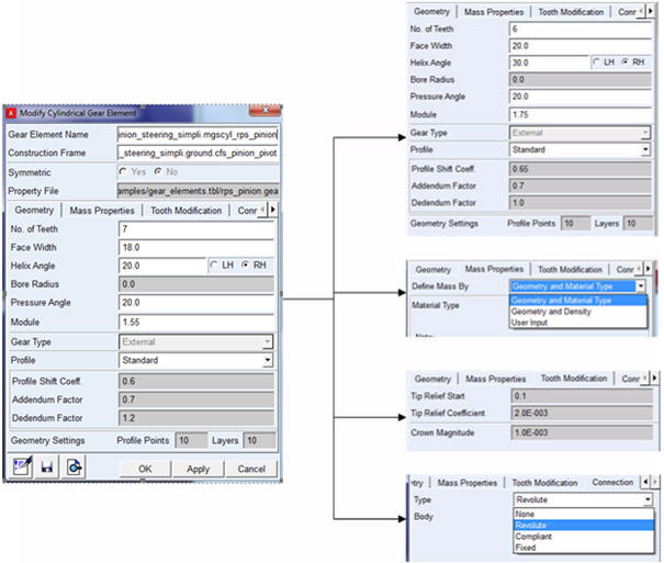
Create gear element
■Specify name of the gear
■Specify 'construction frame' as reference ('Z' axis of construction frame is aligned with rotational axis of gear)
■Specify gear element parameters:
♦Refer a property file (from 'acar_shared database')
♦Specify the input parameters manually
♦Save 'property file' will overwrite existing property file
♦Specify mass properties
♦Specify Tooth modification parameters if applicable
■Specify Connection part and type of connection
■Specify Symmetry
♦If selected reference frame is of type 'single' symmetry will be 'single'
♦If selected reference frame is of type 'left' or 'right' user can choose symmetry as 'yes/no'
General Layout sample for dialog box
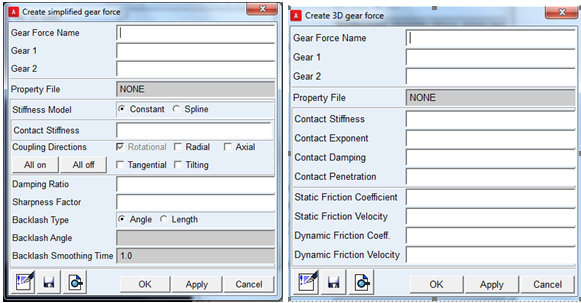
To create gear force
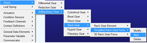
■Select required gear force type (simplified/3D/Detailed)
■Enter gear force parameters:
■Select a gear_force property file from 'acar_shared database'.
■Enter input parameters manually.
■Symmetry
♦Gear force symmetry is inherited from gear elements.
♦If any of gear elements (gear 1 or gear 2) is symmetric, then gear_force will be symmetric.
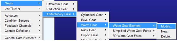
Modifying a gear
Gear element or gear force can be modified either by RMB modify (GUI or model browser) or using 'modify' dialog box.
Deleting a gear
Gear pair should be deleted in reverse order as they were created.
A gear force should be deleted first as it has dependency on gear elements.
Gear element/force can be deleted using RMB delete (GUI or model browser) or using 'delete' dialog box.
Applying actuator motion to a gear
As the joint under gear element instance does not have naming convention as (j[ok][lrs]{rev,tra,cyl}_*), user will have to clear the filter to '*' while browsing for joints under gear elements. Alternatively one can use a filter like [jg][oke][lrsa]{rev,tra,cyl,r}_*
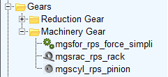
Model Browser Representation
All machinery gear elements will be named as : mg[lrs]{cyl,bev,rac,wrm,hyp,for,pla}_*
Where,
■mg - stands for machinery gear
■[lrs] - represents symmetry
■{cyl,bev,rac,wrm,hyp,pla} - denotes cylindrical, bevel, rack, worm. hypoid and planetary gears respectively
■{for} - denotes gear force
Model browser representation will look like below:
Subsystem parameters for Machinery Gear
In a subsystem file, Machinery Gear elements have the block header 'MACHINERY_GEAR'. It lists both Machinery Gear elements as well as gear force subsystem parameters. You can manually edit the gear subsystem parameters which will be reflected in the modeling session after importing the subsystem file.