Communicators
Communicators are the key elements in template-based products that enable the exchange of information between subsystems, templates, and the test rig in your assembly.
An assembly requires two directions of data transfer between its subsystems. To provide for these two directions of data transfer, the template-based products have two types of communicators:
■Input communicators - Request information from other subsystems or test rigs.
■Output communicators - Provide information to other subsystems or test rigs.
In Adams Car for example, a mount communicator in the rack and pinion steering templates outputs the rack part name so that tie rods of suspension templates can attach to the rack. In addition, a mount communicator in the steering template inputs a part name. The steering template uses the part name to determine where to attach the steering column.
Learn more about communicators:
Creating/Modifying Input Communicators
You can create or modify input communicators as explained next. You must be in template-builder mode to do this.
To create/modify input communicators:
1. From the Build menu, point to Communicator, point to Input, and then select New/Modify.
2. Press F1 and then follow the instructions in the dialog box help for Create/Modify Input Communicator.
3. Select OK.
Creating/Modifying Output Communicators
You can create or modify output communicators as explained next. You must be in template-builder mode to do this.
To create/modify output communicators:
1. From the Build menu, point to Communicator, point to Output, and then select New/Modify.
2. Press F1 and then follow the instructions in the dialog box help for Create/Modify Output Communicator.
3. Select OK.
Communicator Entity Class
The class of a communicator indicates the kind of information it exchanges. For example, communicators of the class marker exchange a location and an orientation through a construction frame name and a part name. The classes of communicators and the information that each class exchanges are listed in table Communicator Entity Class. The classes apply to both input and output communicators.
In Adams Car, and Adams Driveline, communicators can be either single or be part of a symmetrical pair, either left or right. The table below provides additional information about entity classes.
The class: | Exchanges: |
|---|---|
The following entity classes do not have symmetry and, therefore, are always single, by default: | |
Array | Adams Solver array name. |
Differential equation | Differential equation name. |
Motion | Motion name. |
Parameter variable name. | |
Spline | Spline name. |
Solver variable | Adams Solver variable name. You must use an Adams Solver variable, not an Adams View variable. Unlike an Adams View variable, an Adams Solver variable's computation occurs during analysis. Your template-based product generates Adams Solver variables as state variables. |
The following entity classes have symmetry: | |
Mount | Part name to provide connections between subassemblies. As a shortcut, the template-based products also automatically create input mount communicators when you create a mount part. |
Marker | Creation of a marker output communicator results in the creation of a new marker whose location is defined by a user-input construction frame and which is located on a user-input part. The identity of this marker is passed through this communicator to provide both location and part information. If the construction frame is part of a symmetrical pair, the template-based products create an input communicator for each construction frame in the pair. |
Joint | Joint name. |
Joint-for-motion | Joint name. |
Bushing | Bushing name. |
Location | The location of the named hardpoint or construction frame. If the hardpoint is part of a symmetrical pair, the template-based products create two input communicators, one for each hardpoint in the pair. |
Part | Part name. |
Orientation | The orientation of the named construction frame. |
Real parameter | A parameter variable name of the type real. |
Integer parameter | A parameter variable name of the type integer. |
Communicator Minor Roles
Each communicator has a minor role. A minor role defines the communicator's position in the assembly. The template-based products provide you with minor roles, as shown in the following table:
This template-based product: | Has these communicator minor roles: |
|---|---|
Adams Car | ■any (see Communicator Minor Role: Any ) ■inherit (see Communicator Minor Role: Inherit ) ■front (see Communicator Minor Role: Front, Rear, Middle) ■rear (see Communicator Minor Role: Front, Rear, Middle) ■trailer |
You can define a communicator's minor role when you create it. For example, if you want to provide input to or output from subsystems of specific roles, then you set the minor role for communicators when you create them. We recommend, however, that you do not set a communicator's minor role. Instead, let the subsystem determine the minor role by setting it to inherit, in which case the communicator inherits the minor role from the subsystem in which it is embedded. For example, in Adams Car a suspension template might be used to define either a front or rear suspension subsystem. By letting the subsystem determine the minor role, the assembly process attaches a steering system to the front suspension and not to the rear.
Communicator Naming
After you create a communicator, your template-based product assigns a prefix to the name. For example, it creates a prefix, cil_ where:
■ci indicates it is an input communicator. If it were an output communicator, the template-based product would use co.
■l indicates it is for the left side of a symmetrical pair. If it were for the right side, the template-based product would use an r. If it were a single communicator, it would have an s (cis).
If you create a mount part, your template-based product automatically creates an input communicator of the class mount. It uses the name of the mount part as the name of the communicator and appends the prefix ci[lrs]_ to it, depending on whether or not it is a left, right, or single communicator. For example, if you create a mount part of mtl_rack_mount, your template-based product creates an input communicator with the name cil_rack_mount, where the l indicates it is for the left side.
As you name communicators, you should ensure that any input and output communicators that exchange information have identical matching names. In Adams Car for example, the name you give to communicators that exchange a part name during assembly might be cil_strut_mount and col_strut_mount, each of which has a default matching name of strut_mount. In addition, if you are working with MSC Software templates, you must ensure that you use the same naming conventions as the MSC Software templates. Learn about matching communicators.
Matching Communicators During Assembly
For a pair of communicators to exchange information during assembly, the communicators must:
■Have identical matching names.
■Be of opposite types (one input, one output).
■Be of the same symmetry type (left, right, or single).
■Be of the same class (exchange the same type of information).
■Have the same minor role or be assigned a role of any.
■Have the same subsystem index (defaults to inherit).
If all pieces of information match, your template-based product determines an input/output communicator pair.
If an input communicator does not have a corresponding output communicator, your template-based product returns a warning message, and, if the input communicator belongs to the class mount, the template-based product assigns the mount part to ground. You can still analyze the model even if it does not have matching communicators. In fact, you may find this helpful if you want to run an analysis of a subsystem without attaching another subsystem to it.
Keep in mind that the matching name can contain more than one string. By default, the matching name is derived from the communicator name, but the user can change the matching name and/or specify additional matching names.
In Adams Car for example, the following pairs of input and output communicators match and exchange data during assembly.
Sample of Matching Input and Output Communicators
The pair: | Belongs to the class: | From minor role: | To minor role: | Matching name: | Subsystem index: | Subsystem minor role: |
|---|---|---|---|---|---|---|
cil_strut_mount | mount | front | - | strut_mount | inherit | any |
col_strut_mount | mount | - | inherit | strut_mount | inherit | front |
cil_strut_mount | mount | any | - | strut_mount | inherit | any |
col_strut_mount | mount | - | front | strut_mount | inherit | any |
cil_strut_mount | mount | inherit | - | strut_mount | inherit | any |
col_strut_mount | mount | - | any | strut_mount | inherit | any |
cis_hitch_location | location | inherit | - | hitch_location | inherit | trailer_2 |
cos_aft_hitch_location | location | - | inherit | hitch_location | next | trailer |
If your assembly contains multiple subsystems with the same major and minor roles, they will be internally indexed. For example, imagine a trailer model which uses the same suspension at three locations. You can include a subsystem named trailer_suspension (major role: suspension, minor role: trailer) three times. Internally, these subsystems' minor roles will be indexed. The minor role of the first suspension will be "trailer", the second minor role becomes "trailer_2", the third becomes "trailer_3" and so on. If the rest of your trailer assembly contains communicators that match these minor roles + subsystem indices ("trailer", "trailer_2", "trailer_3"), the communicators will match successfully.
You can match an input communicator with only one output communicator. You can, however, match an output communicator with any number of input communicators.
Note: | You should always check the warning messages during the assembly, especially if the warning refers to an input communicator of the mount class that does not get assigned, and is therefore attached to ground. |
Displaying Communicator Information
You can display information about communicators in each template or test rig. The communicator information includes the names of the communicators, their classes, and minor roles. You can choose to display all types and classes of communicators in the templates and test rigs or display only a specified set of types and classes.
To display information about communicators:
1. From the Build menu, point to Communicator, and then select Info.
3. Select OK.
Information window appears. It displays the communicator information for each template or test rig, grouped by each class of communicator that you selected.
Testing Communicators
You can perform a test to verify that you have correctly specified input and output communicators in your template. You can use this test to determine whether or not you need to add or modify communicators to correctly create an assembly.
When you perform the test, you specify the model names of one or more existing templates or test rigs. Although you can specify a single template, you should specify all the templates containing communicators that transfer information between the selected template. You must specify a minor role for each template, subsystem, or test rig you chose to test.
After you perform the test, your template-based product lists the matching input and output communicators, the unmatched input communicators, and the unmatched output communicators for the templates, subsystems, and test rigs you selected. You can save the test information to a file.
To test communicators:
1. From the Build menu, point to Communicator, and then select Test.
3. Select OK.
The Information window appears. It contains a list of the communicators that match other communicators and a list of those that do not. It shows the matched communicators followed by the unmatched communicators. The lists include the names of the input and output communicators and the names of the templates to which they belong. Often, you'll see many communicators that are unmatched. Many of these communicators are related to subsystems or test rigs that you do not currently have open.
If you want to fully test the communicators in your template, you should open the other templates with which you want the template to communicate. In Adams Car for example, if you are creating a suspension template, the template must be able to communicate with a steering template and the suspension test rig.
Communicators in the Suspension Test Rig
The following tables describe the input and output communicators in the suspension test rig (.__MDI_SUSPENSION_TESTRIG). In the tables, the notation:
■[lr] indicates that there is both a left and right communicator of the specified name, as in ci[lr]_camber_angle.
■s indicates a single communicator, as in cis_steering_rack_joint.
Communicators in the Suspension Test Rig
The communicator: | Belongs to the class: | From minor role: | Receives: |
|---|---|---|---|
ci[lr]_camber_angle | parameter_real | any | Camber angle value from the suspension subsystem. Sets the correct orientation of the test rig wheels. |
ci[lr]_diff_tripot | location | any | Location of the differential. |
ci[lr]_toe_angle | parameter_real | any | Toe angle value from the suspension subsystem. Sets the correct orientation of the test rig wheels. |
ci[lr]_suspension_mount | mount | any | Part to which the test rig wheels can attach. |
ci[lr]_suspension_upright | mount | any | Upright part from suspension subsystem. |
ci[lr]_jack_frame | mount | any | Not matched (fixed to ground). |
ci[lr]_wheel_center | location | any | Location of the wheel center from the suspension subsystem. Test rig wheels attach to the suspension at that location. |
cis_driveline_active | parameter_integer | any | Integer value stored in the suspension template/subsystem that indicates the activity of the drivetrain. |
cis_powertrain_to_body | mount | any | Part to which differential outputs are constrained. |
cis_leaf_adjustment_steps | parameter_integer | any | Integer value stored in the leaf spring template (currently not available). |
cis_steering_rack_joint | joint_for_motion | any | Steering-rack translational joint from the steering subsystem. |
cis_steering_wheel_joint | joint_for_motion | any | Steering-wheel revolute joint from the steering subsystem. |
cis_suspension_parameters_ARRAY | array | any | Array used in the suspension characteristic calculations; comes from the suspension subsystems. |
Output Communicators in Suspension Test Rig
The communicator: | Belongs to the class: | From minor role: | Outputs: |
|---|---|---|---|
cos_leaf_adjustment_multiplier | array | any | Leaf Spring toolkit. It is currently not supported in the standard product. |
cos_characteristics_input_ARRAY | array | any | Suspension, vehicle, and test-rig parameters array IDs used by suspension characteristics calculations routines. |
co[l,r]_tripot_to_differential | mount | any | Outputs the ge[lr]_diff_output parts. |
cos_tire_forces_array_left | array | any | Outputs array of Adams IDs used by the conceptual suspension module. |
cos_tire_forces_array_right | array | any | Outputs array of Adams IDs used by the conceptual suspension module. |
Communicators in the SDI Test Rig
The following tables describe the input and output communicators in the SDI test rig (.__MDI_SDI_TESTRIG). In the tables, the notation [lr] indicates that there is both a left and right communicator of the specified name.
Input Communicators in SDI Test Rig
The communicator: | Belongs to the class: | From minor role: | Receives: |
|---|---|---|---|
cis_aero_drag_force | solver_variable | any | The aerodynamic drag force from the body template. It is used in Adams SmartDriver simulations. |
cis_aero_frontal_area | parameter_real | any | Frontal area of the vehicle, used in aerodynamic force calculations in SmartDriver. |
cis_air_density | parameter_real | any | Density of the air, used in aerodynamic force calculations in SmartDriver. |
cis_body_subsystem | mount | inherit | Output from the body subsystem. It indicates the part that represents the body. |
cis_chassis_path_reference | marker | any | Marker from the body subsystem. It is used to measure path, roll, and sideslip error in a constant radius cornering maneuver. |
cis_clutch_displacement_ic | solver_variable | any | The clutch initial displacement (wind-up due to engine crankshaft torque at static equilibrium) from the powertrain template. |
cis_crankshaft_ratio | parameter_real | any | Provided to Standard Driver Interface, but not currently used. |
cis_diff_ratio | parameter_real | any | Real parameter variable for final drive ratio, from the powertrain subsystem, used by SmartDriver. |
cis_downforce_coefficient | parameter_real | any | Downforce coefficient, used in aerodynamic force calculations in SmartDriver. |
cis_downforce_brake_coefficient | parameter_real | any | Downforce coefficient during braking, used in aerodynamic force calculations in SmartDriver. |
cis_drag_coefficient | parameter_real | any | Drag coefficient, used in aerodynamic force calculations in SmartDriver. |
cis_drag_brake_coefficient | parameter_real | any | Drag coefficient during braking, used in aerodynamic force calculations in SmartDriver. |
cis_driver_reference | marker | any | Marker from the body subsystem. It is used to create the iso_eas marker on ground, which provides the reference system for the driving machine (so it should be oriented with Z up, X forward, and Y to the left.) It is also used to measure body displacement, velocity and acceleration and distance traveled. |
cis_drive_torque_bias_front | parameter_real | any | Nominal percentage of torque sent to the front wheels. 1.0 = front wheel drive, 0.0 = rear wheel drive, 0.5 = all-wheel drive. Used by SmartDriver and the SVC event. |
cis_engine_idle_speed | parameter_real | any | Engine idle rpm, from engine or powertrain subsystem. Used to set initial engine speed if simulation begins in neutral or with clutch pedal down. Defaults to 750. |
cis_engine_map | spline | any | Engine torque/speed/throttle map from engine or powertrain subsystem. Used by Standard Driver Interface, cis_max_engine_braking_torque and cis_max_engine_driving_torque are relied upon if not available. |
cis_engine_rpm | solver_variable | any | Adams Solver variable for engine speed, in revolutions per minute, from the powertrain subsystem. Used by Standard Driver Interface. |
cis_engine_speed | solver_variable | any | Adams Solver variable for engine speed, in radians per second, from the powertrain subsystem. Used by Standard Driver Interface. |
cis_engine_speed_limit | parameter_real | any | Output from powertrain subsystem (maximum engine rpm value, used for shifting strategy). Defaults to 6500. |
cis_engine_stall_speed | parameter_real | any | Output from powertrain subsystem (minimum engine rpm value, used for shifting strategy and to limit initial engine speed setting when appropriate). Defaults to 500. |
cis_front_aero_location | marker | inherit | Marker used to measure the distance from gyro location to aero force location. Used by the Standard Driver Interface. |
cis_max_brake_value | parameter_real | any | Output from brake subsystem (maximum brake signal value). |
cis_max_engine_braking_torque | solver_variable | any | Output from engine or powertrain subsystem, gives lower (braking) limit on available engine torque at current engine speed. |
cis_max_engine_driving_torque | solver_variable | any | Output from engine or powertrain subsystem, gives upper (driving) limit on available engine torque at current engine speed. |
cis_max_gears | parameter_integer | any | Output from powertrain (maximum number of allowed gears). |
cis_max_rack_displacement | parameter_real | any | Output displacement limits from steering subsystem. Used by the Standard Driver Interface. |
cis_max_rack_force | parameter_real | any | Output force limits from steering subsystem. Used by the Standard Driver Interface. |
cis_max_steering_angle | parameter_real | any | Output angle limits from steering subsystem. Used by the Standard Driver Interface. |
cis_max_steering_torque | parameter_real | any | Output from steering subsystem. |
cis_max_throttle | parameter_real | any | Output from powertrain (maximum value of throttle signal). |
cis_measure_for_distance | marker | any | Marker used to measure the distance traveled in the forward direction of the vehicle, from the body subsystem. |
cis_powertrain_type | parameter_integer | any | Classification for powertrain (manual, automatic and so on.) from powertrain subsystem. |
cis_steering_rack_joint | joint_for_motion | front | Steering-rack translational joint from the steering subsystem. |
cis_steering_wheel_joint | joint_for_motion | front | Steering-wheel revolute joint from the steering subsystem. |
cis_svs_trim_part | part | any | |
cis_transmission_efficiency | parameter_real | any | Overall efficiency of driveline, used by smartdriver to calculate target velocity profiles. Can be specified by the powertrain subsystem, defaults to 1.0. |
cis_transmission_input_omega | solver_variable | any | The transmission input speed variable from the powertrain template. |
cis_transmission_spline | spline | any | Spline for transmission gears (output from powertrain: reduction ratios for every gear). |
ci[lr]_front_suspension_mount | mount | front | The hub parts (wheel carriers) from suspension templates (front and rear). |
ci[lr]_rear_suspension_mount | mount | rear | The hub parts (wheel carriers) from suspension templates (front and rear). |
ci[lr]_svs_ride_height_front | marker | front | |
ci[lr]_svs_ride_height_rear | marker | rear | |
ci[lr]_tire_force_front | force | front | The tire force from the wheel templates (front and rear). |
ci[lr]_tire_force_rear | force | rear | The tire force from the wheel templates (front and rear). |
ci[lr]_wheel_center_front | location | front | The location of the (left and right) wheel centers from suspension templates (front). |
ci[lr]_wheel_center_rear | location | rear | The location of the (left and right) wheel centers from suspension templates (rear). Used to locate the gyro location (midpoint between left and right wheel centers) for the driving machine (a pitch and roll stabilized point on the vehicle that should follow prescribed paths for machine steering control events.) |
Output Communicators in SDI Test Rig
The communicator: | Belongs to the class: | From minor role: | Outputs: |
|---|---|---|---|
cos_aero_pitch_angle | parameter_real | any | Outputs parameter real used by aerodynamic force UDE to calculate coefficients at that angle |
cos_aero_pitch_angle_brake | parameter_real | any | Outputs parameter real used by aerodynamic force UDE to calculate coefficients at that angle (braking) |
cos_brake_demand | solver_variable | any | Outputs brake demand used by conceptual brake module. |
cos_clutch_demand | solver_variable | any | Outputs brake demand used by conceptual powertrain module. |
cos_initial_engine_rpm | parameter_real | any | Outputs initial engine rpm used by conceptual powertrain module. |
cos_sse_diff1 | diff | any | Outputs differential equation used by conceptual powertrain module. |
cos_std_tire_ref | location | any | Outputs location of tire reference used by chassis for ground height reference. |
cos_throttle_demand | solver_variable | any | Outputs throttle demand used by conceptual powertrain module. |
cos_transmission_demand | solver_variable | any | Outputs transmission demand used by conceptual powertrain module. |
Communicators in the Suspension Parameter Measurement Machine (SPMM) Test Rig
The following tables describe the input and output communicators in the SPMM test rig (.__MDI_SPMM_TESTRIG).
In the tables, the notation:
■[lr] indicates that there is both a left and right communicator of the specified name, as in ci[lr]_wheel_center_front
■s indicates a single communicator, as in cis_body_subsystem.
Input Communicators in the SPMM Test Rig
The communicator | Belongs to the class: | From minor role: | Receives: |
|---|---|---|---|
ci[lr]_suspension_mount_front | mount | front | The hub parts (wheel carriers) from suspension (front) |
ci[lr]_suspension_mount_rear | mount | rear | The hub parts (wheel carriers) from suspension (front) |
cis_body_subsystem | mount | any | Output from the body subsystem. It indicates the part that represents the chassis part. |
cis_flexible_body | mount | any | Output from the body subsystem. It indicates the flexible part that represents the chassis part. Note: Add matching name 'flexible_body' in the output communicator name 'cos_body' or 'cos_body_subsystem'. |
cis_steering_wheel_joint | Joint_for_motion | any | Steering-wheel revolute joint from the steering subsystem. |
cis_suspension_parameters_ARRAY_front | array | front | Suspension parameter array from the suspension subsystem (front) |
cis_suspension_parameters_ARRAY_rear | array | rear | Suspension parameter array from the suspension subsystem (rear) |
ci[lr]_bedplate_front_loc | location | front | Location of the nodes on flexible chassis of body subsystem. The spherical joints from test rig attaches to the flexible body at that location. (This communicator is only used for flexible chassis subsystem) |
ci[lr]_bedplate_rear_loc | location | rear | Location of the nodes on flexible chassis of body subsystem. The spherical joints from test rig attaches to the flexible body at that location. (This communicator is only used for flexible chassis subsystem) |
Output Communicators in SPMM Test Rig
The communicator | Belongs to the class: | From minor role: | Outputs: |
|---|---|---|---|
cos_characteristics_input_ARRAY_front | array | front | Suspension, vehicle, and test-rig parameters array IDs. This is just a placeholder. |
cos_characteristics_input_ARRAY_rear | array | rear | Suspension, vehicle, and test-rig parameters array IDs. This is just a placeholder. |
Matching Communicators with Test Rigs
When you create a template, you must meet the following conditions to ensure that an analysis will work with your new template:
■The template must be compatible with other templates and with the test rigs, for example, the .__MDI_SUSPENSION_TESTRIG. The template must also contain the proper output communicators.
■If the template is a suspension template (for example, its major role is suspension), the template must contain a suspension parameters array. The suspension parameters array identifies to the suspension analysis how the steer axis should be calculated and whether the suspension is independent or dependent.
For example, for a suspension template to be compatible with the suspension test rig, the suspension template must contain either the mount or the upright output communicators. In the following table, the notation [lr] indicates that there is both a left and right communicator of the specified name.
Output Communicators in Suspension Templates
The communicator: | Belongs to the class: | From minor role: | Receives: |
|---|---|---|---|
co[lr]_suspension_mount | mount | inherit | suspension_mount |
co[lr]_suspension_upright | mount | inherit | suspension_upright |
co[lr]_wheel_center | location | inherit | wheel_center |
co[lr]_toe_angle | parameter_real | inherit | toe_angle |
co[lr]_camber_angle | parameter_real | inherit | camber_angle |
The co[lr]_suspension_mount output communicators publish the parts to which the test rig wheels should mount. As you create these communicators, ensure that you set their minor role to inherit. By setting the minor role to inherit, the communicator takes its minor role from the minor role of the subsystems that use your suspension template.
The co[lr]_wheel_center output communicators publish the location of the wheel centers to the test rig so the test rig can locate itself relative to the suspension. As you create these types of communicators, make sure that you also leave their minor role set to inherit.
The toe and camber communicators (co[lr]_toe_angle and co[lr]_camber_angle) publish, to the test rig, the toe and camber angles set in the suspension so the test rig can orient the wheels correctly.
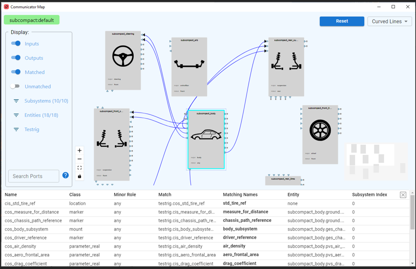
Communicator Map
Overview
The Communicator Map provides a graphical display of the Communicator matches in an Assembly.
This map lets the user quickly identify:
■Input vs Output Communicators across the subsystems,
■Communicators that match,
■Communicators that are unmatched,
■Input Mount Communicators that are connected to ground
■Which subsystems are connected to which other subsystems.
Click on the  icon when viewing an Assembly to display the Communicator Map. The Communicator Map may also be displayed:
icon when viewing an Assembly to display the Communicator Map. The Communicator Map may also be displayed: ■Using menu picks: when viewing an Adams Car Assembly: Setup à Model Info à Communicator Map…
■From Template Builder: using the new Graphical option in the Test Communicators dialog box from Template Builder: Build → Communicator → Test…
The main components of the Communicator Map are described below and are referred to as:
■Display Filters
■Model Name Display
■Communicator Table
Window Overview & Common Operations
The main Communicator Map area shows model subsystems as unique blocks. Matching Communicator names between the blocks are shown as connection lines.
Subsystem blocks, connection lines and Communicator port icons all have informative tooltips that reveal information about the respective items. Left-mouse click on objects to select them and expose all additional information in a tabular format.
Use the following to move, zoom, arrange and position items:
■Pan/Translate: left-mouse and drag on the background OR right-mouse and drag anywhere
■Zoom: mouse wheel scroll. Hold CTRL to center zoom about current mouse cursor location.
■Move a subsystem: left-mouse and drag
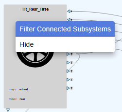
■Hide: right-mouse on a subsystem block and select Hide
■Select Nothing: left-mouse in empty background area
■Only Show Connected Subsystems: right-mouse on a subsystem block and select Filter Connected Subsystems to display only the blocks that are connected to the current one.
Display Filters
Use the Display panel to filter the information shown in the Communicator Map.
Toggles: Inputs, Outputs, Matched & Unmatched:
The main toggles for Inputs/Outputs and Matched/Unmatched control much of the information available. Note the following:
1. Connecting lines in the Map are shown when Matched is ON. Both Inputs and Outputs must also be ON to see connecting lines.
2. Unmatched shows all Communicators in a subsystem. This is turned OFF by default to simplify the display of information. Typically, more Warning indicators appear when Unmatched is ON, so use this to check the validity of connections.
Subsystem & Entities Filters:
The Subsystems filter lets you reduce the number of displayed subsystems in the Map. Simply which subsystems are to be displayed and dismiss the selection box to update the Map view.
Note: | To quickly reduce the number of subsystems displayed, right-click on a subsystem of interest and select Filter Connected Subsystems. This sets the Subsystems filter to only display those blocks that are connected to the current one. |
The Entities filter allows you to specify the types of Communicators (marker, mount, parameter, etc) that are shown. All Entities are displayed by default, but it is easy to, for example, display only Communicators of type Mount.
Testrig Display:
The Testrig subsystem has many Communicators, so the user has unique control over how these are displayed. The default ‘Compact’ method shows Testrig connections as special ‘T’ icons, as shown:
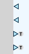
It is also possible to display the testrig as a normal block (‘Block’), a flat block at the bottom of the map (‘Base Block’) or to hide it (‘Hidden’).
Search for Communicators:
The Search Ports field accepts a search string that is used to identify Communicator ports in the Map. Enter a search string (ie: ‘wheel’ or ‘brake’) – select ENTER and all Communicator ports containing this string are highlighted with a green background.
Model Name Display
The current model name, and variant, are displayed in the top-left corner of the window when the Communicator Map is displayed from an Assembly in Adams Car.
When the Communicator Map is displayed from Template Builder in Adams Car, the names of the selected templates will be shown as a list in the top-left corner.
Communicator Table
Shows detailed information for Communicators such as Class, Minor Role, Match, Matching Names, Entity and more. Close the table by clicking the X icon, or clicking in the background of the main map. Tabular output is shown when the following objects are selected:
■Subsystem: lists all Communicators for the subsystem, subject to the active Display filters.
■Communicator Port: a single row of data for this object.
■Matched Line: two rows of data; one for each of the associated Communicators in the match.