Running Analyses
Introducing Analyses
Adams Car Ride allows you to create virtual prototypes of vehicle subsystems, and analyze the virtual prototypes much like you would analyze the physical prototypes.
Using Adams Car Ride to analyze a virtual prototype is much like requesting a test of a physical prototype. When testing in Adams Car Ride, you specify the following:
■The virtual prototype to be tested - You specify the virtual prototype by opening or creating an assembly that contains the appropriate components, or subsystems, that make up the prototype. For example, you create a full-vehicle assembly containing suspension, steering, body, brakes, wheels, and so on.
■The kind of Analysis you'd like performed - Depends on the type of model and test rig that you have opened. You can perform analyses of components (using the component test rig), fourpost and vibration analyses (using the fourpost test rig).
■The analysis inputs to be used - You specify the inputs to the analysis by typing them directly into an analysis dialog box or by selecting a loadcase file that contains the desired inputs from an Adams Car Ride database. Learn about Loadcase Files.
After specifying the prototype assembly and its analysis, Adams Car Ride, like your company’s testing department, applies the inputs that you specified and records the results. To understand how your prototype behaved during the analysis, you can plot the results. After viewing the results, you can modify the prototype and analyze it again to see if your modifications improved its behavior.
Each kind of analysis that you perform requires a minimum set of subsystems. For example, a full-vehicle analysis requires front and rear suspension subsystems, front and rear wheel subsystems, one steering subsystem, and one body subsystem. Before you can create an assembly and perform an analysis in Adams Car Ride, you must open or create the minimum set of subsystems required.
Setting up Component Analyses
You can use a component analysis to calculate the dynamic stiffness and loss angle of a frequency-dependent bushing or damper.
To set up a component analysis:
1. From the Ride menu, point to Component Analysis, and then select Component-Model Test Rig.
3. Select OK.
Setting up Full-Vehicle Analyses
You can use a full-vehicle analysis to investigate a car's ride-quality characteristics.
To set up a full-vehicle analysis:
1. From the Ride menu, point to Full-Vehicle Analysis, and then select Four-Post Test Rig.
2. Press F1 and then follow the instructions in the dialog box help for Full-Vehicle Analysis: ARIDE_FOUR_POST_TESTRIG.
3. Select OK.
Setting up Full-Vehicle Vibration Analyses
You can use a full-vehicle vibration analysis to analyze the behavior of your linearized vehicle model in the frequency domain. This includes analyses of vibration transmission frequency responses, natural frequencies, mode shapes, and damping ratios.
To set up a vibration full-vehicle analysis:
1. From the Ride menu, point to Full-Vehicle Vibration Analysis, and then select Four-Post Test Rig.
2. Press F1 and then follow the instructions in the dialog box help for Full-Vehicle Vibration Analysis: ARIDE_FOUR_POST_TESTRIG.
3. Select OK.
Controlling Analysis Output Files
Your template-based product lets you control the type and content of files an analysis outputs. You can specify whether an analysis outputs a graphics file or results file. Graphics files contain time-dependent data describing the position and orientation of each part in the model. Results files contain a basic set of state variable information that Adams Solver calculates during a simulation.
Your template-based product automatically reads the files that an analysis outputs.
If any subsystems within the assembly being analyzed contain flexible bodies, your template-based product automatically outputs a results file, regardless of the specifications you made.
To specify analysis output files:
1. From the Settings menu, point to Solver, and then select Output Files.
The Output Files dialog box appears.
2. Select the types of files you want to output.
3. Select OK.
Setting up ISO Ride Index
It has been proven that vibration results in musculoskeletal disorders of the hand and arms, the neck and the back. There are two types of occupational vibration: segmental and whole body. Segmental vibration is transmitted through the hands and arms; while to whole body vibration (WBV) is transmitted through the body's supporting surfaces such as the legs, the back and the buttocks. Human bodies are exposed to WBV from various sources such as standing on a vibration platform, floor surface, driving, construction, manufacturing and transportation. Along with musculoskeletal problems, exposure to occupational whole body vibration also presents a health risk to the psychomotor, physiological, and psychological systems of the body.
The primary purpose here is to provide computational means for quantifying WBV as described in ISO 2631/1 procedure in relation to: human health, comfort and perception. Response to WBV depends on the frequency of vibration, acceleration (or magnitude) of vibration, number of contact points and the exposure time.
To set up a ISO Ride Index for full-vehicle analysis:
1. From the Ride menu, point to Full-Vehicle Analysis, and then select ISO Ride Index.
3. Select OK.
To calculate Ride Index for Full-Vehicle Vibration Analysis:
1. From the Ride menu, point to Full-Vehicle Vibration Analysis, and then select ISO Ride index.
3. Select OK.
Examples of Ride Index
Example 1: Health analysis with zero contribution from X and Y direction.
This application of ride index to health concerns the effects of periodic, random and transient vibration on the health of persons in normal health exposed to whole-body vibration during travel, at work and during leisure activities. It applies primarily to seated persons, since the effects of vibration on the health of persons standing, reclining or recumbent are not known.
The guidance is applicable to vibration in the frequency range 0, 5 Hz to 80 Hz which is transmitted to the seated body as a whole through the seat pan. Whole-body vibration exposure may also worsen certain endogenous pathologic disturbances of the spine. Although a dose-effect relationship is generally assumed, there is at present no quantitative relationship available. With a lower probability, the digestive system, the genital/urinary system, and the female reproductive organs are also assumed to be affected.
It generally takes several years for health changes caused by whole-body vibration to occur. It is therefore important that exposure measurements are representative of the whole exposure period.
Evaluation of vibration
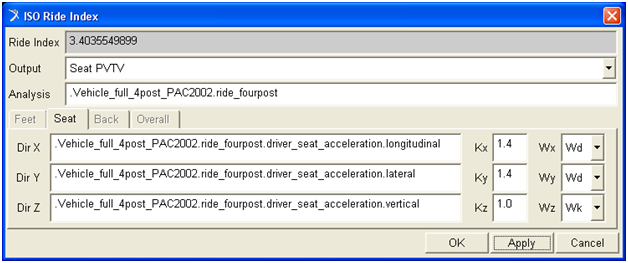
The weighted RMS acceleration shall be determined for each axis (x, y and z) of translational vibration on the surface which supports the person. The assessment of the effect of a vibration on health shall be made independently along each axis. The assessment of the vibration shall be made with respect to the highest frequency-weighted acceleration determined in any axis on the seat pan. The frequency weighting shall be applied for seated persons as follows with the multiplying factors k as Indicated:
X-axis: wd, k = 1.4
Y-axis: wd, k = 1.4
Z-axis: wk, k = 1.0
Time Domain logic array of RIDE_WARMS for Full-Vehicle Analysis
Seat Surface: Logic = {"TIME", "Wd", "Wd", "Wk"}
Seat Back: Logic = {"TIME", "Wc", "Wu", "Wu"}
Feet: Logic = {"TIME", "Wu", "Wu", "Wu"}
Seat Back: Logic = {"TIME", "Wc", "Wu", "Wu"}
Feet: Logic = {"TIME", "Wu", "Wu", "Wu"}
Frequency Domain logic array of RIDE_WARMS for Full-Vehicle Vibration Analysis
Seat Surface: Logic = {"FREQ", "Wd", "Wd", "Wk"}
Seat Back: Logic = {"FREQ", "Wc", "Wu", "Wu"}
Feet: Logic = {"FREQ", "Wu", "Wu", "Wu"}
Seat Back: Logic = {"FREQ", "Wc", "Wu", "Wu"}
Feet: Logic = {"FREQ", "Wu", "Wu", "Wu"}
Note: | When vibration in two or more axes is comparable, the vector sum is sometimes used to estimate health risk. |
Guidance to Health
There are not sufficient data to show a quantitative relationship between vibrations expose effects. Hence, it is not possible to assess whole-body vibration in terms of the probability exposure magnitudes and durations. For recommendation that are mainly based on exposures in the range of 4 h to 8 h, please refer to ISO 2631-1.
Example 2: Comfort analysis.
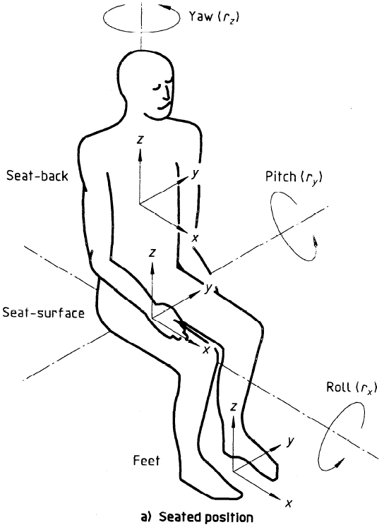
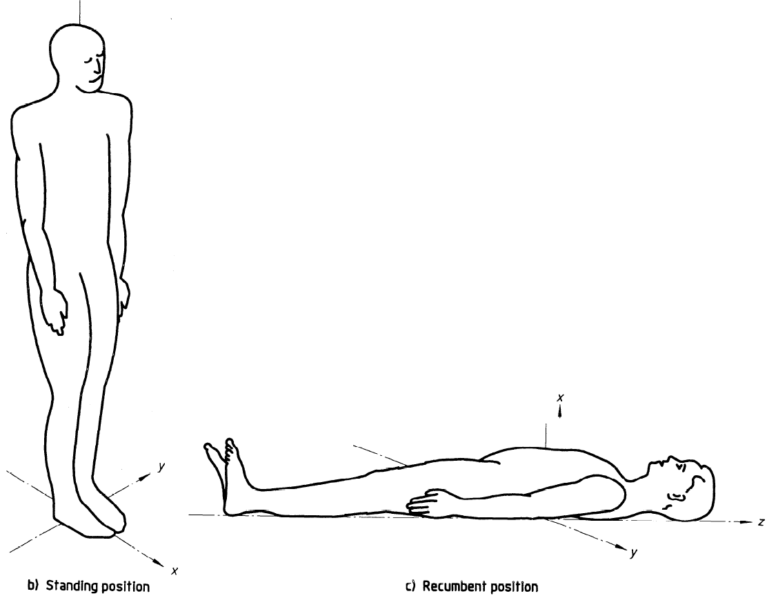
The comfort and perception concerns the estimation of the effect of vibration on the comfort of persons in normal health who exposed to whole-body periodic, random and transient vibration during travel, at work or during leisure activities are for the comfort of seated persons this clause applies to periodic, random and transient vibration in the frequency range 0, 5 Hz to 80 Hz which occurs in all six axes on the seat pan (three translational: x-axis, y-axis and z-axis and three rotational: r,-axis, r,-axis and r,-axis).
It also applies to the three translational axes (x, y and z) at the seat-back and feet of seated persons (see figure below). For the comfort of standing and recumbent persons guidance is provided for periodic, random and transient vibration occurring in the three translational (x, y and z) axes on the principal surface supporting the body. The evaluation procedures make it possible to estimate (from the vibration magnitude, frequency and direction) the likely relative effects on comfort of different types of vibration.
Evaluation of vibration
There is no conclusive evidence to support a universal time dependence of vibration effects on comfort. The weighted RMS acceleration shall be determined for each axis of translational vibration (x-, y- and z-axes) at the surface which supports the person. Frequency weightings used for the prediction of the effects of vibration on comfort are Wc, Wd, We, Wj and Wk. These weightings should be applied as follows with the multiplying factors k as indicated.
a. For seated persons:
X-axis (supporting seat surface vibration): Wd, kx = 1
Y-axis (Supporting Seat Surface vibration): Wd, ky = 1
Z-axis (Supporting Seat Surface vibration): Wk, kz = 1
In some environments, the comfort of a seated person may be affected by rotational vibration on the seat, by vibration of the backrest or by vibration at the feet. Vibration at these positions may be assessed using the following frequency weightings:
rx,-axis on supporting seat surface: We, krx = 0.63 m/rad
ry,-axis on supporting seat surface: We, kry = 0.4 m/rad
rz,-axis on supporting seat surface: We, krz = 0.2 m/rad
X-axis on the backrest: WC, kx = 0.8
Y-axis on the backrest: Wd, ky = 0.5
Z-axis on the backrest: Wd, kz = 0.4
X-axis at the feet: Wk, kx = 0.25
Y-axis at the feet: Wk, ky = 0.25
Z-axis at the feet: Wk, kz = 0.4
b. For standing persons:
X-axis (floor vibration): Wd, kx = 1
Y-axis (floor vibration): Wd, ky = 1
Z-axis (floor vibration): Wk, kz = 1
c. For recumbent persons, when measuring under the pelvis:
Horizontal axes: Wd, ky and kz = 1
Vertical axis: Wk, kx = 1
Time Domain logic array of RIDE_WARMS for Full-Vehicle Analysis
Seat Surface: x-y-z axis Logic = {"TIME", "Wd", "Wd", "Wk"}
Seat Surface: rx-ry-rz axis Logic = {"TIME", "We", "We", "We"}
Seat Back: Logic = {"TIME", "Wc", "Wd", "Wd"}
Feet (sitting): Logic = {"TIME", "Wk", "Wk", "Wk"}
Standing Vertical Recumbent (except head): Logic = {"TIME", "Wu", "Wu", "Wk"}
Standing Horizontal Recumbent: Logic = {"TIME", "Wd", "Wd", "Wu"}
Vertical recumbent (head): Logic = {"TIME", "Wj", "Wj", "Wj"}
Vertical recumbent (head, under pelvis): Logic = {"TIME", "Wk", "Wd", "Wd"}
Frequency Domain logic array of RIDE_WARMS for Full-Vehicle Vibration Analysis
Seat Surface: x-y-z axis Logic = {"FREQ", "Wd", "Wd", "Wk"}
Seat Surface: rx-ry-rz axis Logic = {"FREQ", "We", "We", "We"}
Seat Back: Logic = {"FREQ", "Wc", "Wd", "Wd"}
Feet (sitting): Logic = {"FREQ", "Wk", "Wk", "Wk"}
Standing Vertical Recumbent (except head): Logic = {"FREQ", "Wu", "Wu", "Wk"}
Standing Horizontal Recumbent: Logic = {"FREQ", "Wd", "Wd", "Wu"}
Vertical recumbent (head): Logic = {"FREQ", "Wj", "Wj", "Wj"}
Vertical recumbent (head, under pelvis): Logic = {"FREQ", "Wk", "Wd", "Wd"}
Guidance for comfort
Acceptable values of vibration magnitude for comfort depend on many factors which vary with each application. The following values give approximate indications of likely reactions to various magnitudes of overall vibration total values in public transport. However, as stated before, the reactions at various magnitudes depend on passenger expectations with regard to trip duration and the type of activities passengers expect to accomplish (for example, reading, eating, writing, and so on.) and many other factors (acoustic noise, temperature, and so on.).
Less than 0.315 m/s2 | not uncomfortable |
0.315 m/s2 to 0.63 m/s2 | a little uncomfortable |
0.5 m/s2 to 1 m/s2 | fairly uncomfortable |
0.8 m/s2 to 1.6 m/s2 | uncomfortable |
1.25 m/s2 to 2.5 m/s2 | very uncomfortable |
Greater than 2 m/s2 | extremely uncomfortable |
With respect to comfort and/or discomfort reactions to vibration in residential and commercial buildings, IS0 2631-1 and IS0 2631-2 should be consulted. Experience in many countries has shown that occupants of residential buildings are likely to complain if the vibration magnitudes are only slightly above the perception threshold.
Example 3: Perception analysis.
For the random perception of vibration by standing, sitting and recumbent persons, guidance is provided for vibration occurring in the three translational periodic axes (x, y and z) on the principal surface supporting the body.
Evaluation of vibration
The weighted RMS acceleration shall be determined for each axis (x, y and z) on the principal surface supporting the body. The assessment of the perceptibility of the vibration shall be made with respect to highest weighted RMS acceleration determined in any axis at any point of contact ant any time.
The frequency weightings, Wk for vertical vibration and Wd for horizontal vibration, are used for the prediction of the perceptibility of vibration. There weightings may be applied to the following combinations of posture and vibration axis:
X-, y- and z-axes on a supporting seat surface for sitting person, kx=ky=kz=1
X-, y- and z-axes on a floor beneath a standing person, kx=ky=kz=1
X-, y- and z-axes on a surface supporting a recumbent person (except head), kx=ky=kz = 1
Time Domain logic array of RIDE_WARMS for Full-Vehicle Analysis
Seat Surface: x-y-z axis Logic = {"TIME", "Wd", "Wd", "Wk"}
Seat Surface: rx-ry-rz axis Logic = {"TIME", "We", "We", "We"}
Seat Back: Logic = {"TIME", "Wc", "Wu", "Wu"}
Standing Horizontal Recumbent: Logic = {"TIME", "Wd", "Wd", "Wu"}
Vertical recumbent (head): Logic = {"TIME", "Wj", "Wj", "Wj"}
Vertical recumbent (head, under pelvis): Logic = {"TIME", "Wk", "Wd", "Wd"}
Frequency Domain logic array of RIDE_WARMS for Full-Vehicle Vibration Analysis
Seat Surface: x-y-z axis Logic = {"FREQ", "Wd", "Wd", "Wk"}
Seat Surface: rx-ry-rz axis Logic = {"FREQ", "We", "We", "We"}
Seat Back: Logic = {"FREQ", "Wc", "Wu", "Wu"}
Standing Vertical Recumbent (except head): Logic = {"FREQ", "Wu", "Wu", "Wk"}
Standing Horizontal Recumbent: Logic = {"FREQ", "Wd", "Wd", "Wu"}
Vertical recumbent (head): Logic = {"FREQ", "Wj", "Wj", "Wj"}
Vertical recumbent (head, under pelvis): Logic = {"FREQ", "Wk", "Wd", "Wd"}
Guidance for perception
Fifty percent of alert, fit persons can just detect a Wk weighted vibration with a peak magnitude of 0.015 m/s2. There is a large variation between individuals in their ability to perceive vibration. When the median perception threshold is approximately 0.015 m/s2, the inter-quartile range of responses may extend from about 0.0l m/s2 to 0.02 m/s2 peak. The perception threshold decreases slightly with increases in vibration duration up to one second and very little with further increases in duration. Although the perception threshold does not continue to decrease with increasing duration, the sensation produced by vibration at magnitudes above threshold may continue to increase.