Introducing Adams Car Truck
Adams Car Truck
Welcome to the Adams Car Truck templates from MSC Software. Adams Car is a virtual prototyping product that creates, catalogs, and analyzes full vehicles and vehicle suspensions.
All template-based products have two interfaces: Standard Interface and Template Builder. You can use the Template Builder interface to create and modify components and templates, and the Standard Interface to change parameters and analyze suspension or vehicle assemblies.
This section introduces you to the templates that have been specifically developed for the trucking industry. For general information about building templates, communicators and so on, see the section Building Models in the Adams Car documentation.
The purpose of providing these templates is to have examples available to show how to model multi-axle, multi-subsystem assemblies that are common in the trucking industry. These examples can be modified and populated with vehicle specific data. Adams Car allows you to perform component, subsystem, and full-vehicle analyses in one single environment. With this template-based parametric modeling approach, you can quickly explore multiple what if design scenarios. You can animate vehicle or subsystem motion onscreen, display graphs of key parameters, and produce standardized test reports.
Assembly Configuration
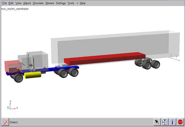
The shared_truck database represents an 18-wheel Tractor and trailer assembly with the following approximate specifications:
GVM - Gross vehicle mass: 38000 kg (distributed over 5 axles)
Wheel & Tire mass: 80kg
Wheelbase: Total -5700mm and cab-to-axle - 4000mm
Approximate weight distribution for suspension test rigs:
msc_susp_front_leafs.asy -> 2 wheels mass = 160kg, sprung mass = 8000kg
msc_truck_susp_3links.asy -> 2 wheels mass = 160kg, sprung mass = 8000kg
msc_susp_driven_axle.asy -> 4 wheels mass = 320kg, sprung mass = 7500kg
msc_susp_trailer_axle.asy -> 4 wheels mass = 320kg, sprung mass = 7500kg
Preferred Solver setting:
Choice of solver: CXX or F77
MAXIT :100
Equilibrium Stability: 0.01
Assembly Variants:
There are two types of brake and leafspring suspension systems available:
■Drum air brake system and disc brake systems
■Beam leafspring and SAE 3link leafspring system
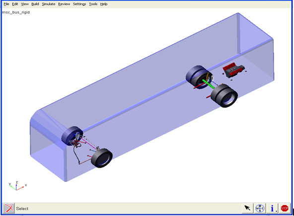
Bus Assembly Database:
The Truck database also provides bus assembly templates and subsystems. The steering, drive axle sub-assemblies are similar to truck database. The bus uses wishbone suspension with anti-roll bar at front and rigid axle suspension at rear. The assembly uses disc brakes on four wheels. The wheelbase is 2000mm. There are no assembly variants for the bus.
Truck Airsprings and Ride Height Sensors
This version contains a new airspring element more applicable to truck designs than the standard airspring available in Adams Car. The Truck airspring uses the same XML-format property file as the standard airspring. The property file defines the diameter (for graphics only), trim length, and 3D force vs. deflection and trim load curve. New ride height sensors may be linked to the airsprings to control ride height. The sensor consists of two links whose locations are determined by three hardpoints. One link is attached to the suspension, the other to the chassis. The angle of the upper link determines whether the airspring trim load is increased or decreased.
Usage
Truck airsprings operate in one of three modes:
■A constant trim load during the entire simulation.
■Automatically adjusted trim load during the initial static equilibrium solution and fixed thereafter.
■Automatically adjusted trim load during the entire simulation.
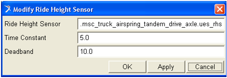
To use the automatic adjustment of trim load, a ride height sensor must exist in the model. A single ride height sensor may be used to control any number of airsprings. The ride height sensor has two parameters: time constant and deadband. The time constant (time units) is used to tune the first-order lag built into the sensor's response. The deadband (angle units) is used to tune the amount of free travel the suspension will be allowed before the airspring trim load is adjusted.
Example
1. Start the Adams Car and load the Adams Car Truck plugin.
2. Open the full-vehicle assembly <atruck_shared>/assemblies.tbl/msc_tractor_unit.asy.
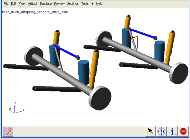
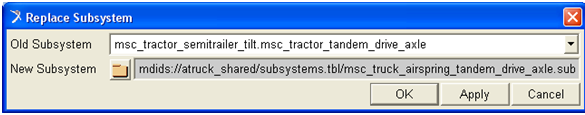
3. Replace the tandem drive axle subsystem by choosing File → Manage Assemblies → Replace Subsystem, and select <atruck_shared>/subsystems.tbl/msc_truck_airspring_tandem_drive_axle.sub as shown in the below figure.
4. Click Apply and OK.
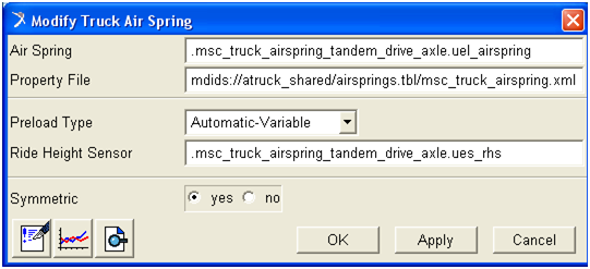
5. Right-click on one of the airsprings and select Modify.
Notice that all four airsprings are currently set up to reference a ride height sensor located at the rear_2 axle. The method is "Automatic-Variable," meaning the trim load may be adjusted during the entire simulation if the sensor moves outside its deadband.
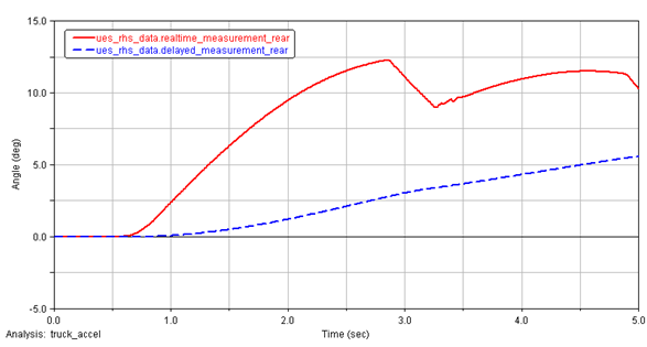
6. Submit a full-vehicle simulation such as straight-line acceleration and open the PostProcessor. Plot results set components ues_rhs_data.realtime_measurement_rear and delayed_measurement_rear as shown in the below figure.
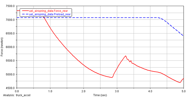
7. Plot results set components uel_airspring_data.Force_rear and Preload_rear, and notice that the preload changes if the delayed_measurement exceeds deadband/2 as shown in the below figure.