Using MATLAB/Code Generation
For more information on Control System Import in MATLAB, see the tutorial entitled 'Getting Started Using Adams Controls'. This tutorial gives you an overview of the four-step process of adding controls to an Adams model. The example also includes tutorials for each of the controls applications you can use with Adams Controls: Co-simulation, Function evaluation, and Control System Import with both Easy5 and MATLAB. See the Examples section to find this tutorial.
Software Requirements
This example requires licenses for Adams Solver, Adams View, and Adams Controls. It also requires licenses for MATLAB/Simulink/Real-Time Workshop, and using the version(s) that are compatible with Adams. The exact versions supported can be found under "Supported Versions of Integration Products" in the following link:
Compilers supported by both Adams and MATLAB/Code Generation must also be available (for example, Microsoft Visual Studio 2013) - again, see the link above for exact details. These products are all assumed to be on the same machine for this tutorial.
Solver Settings
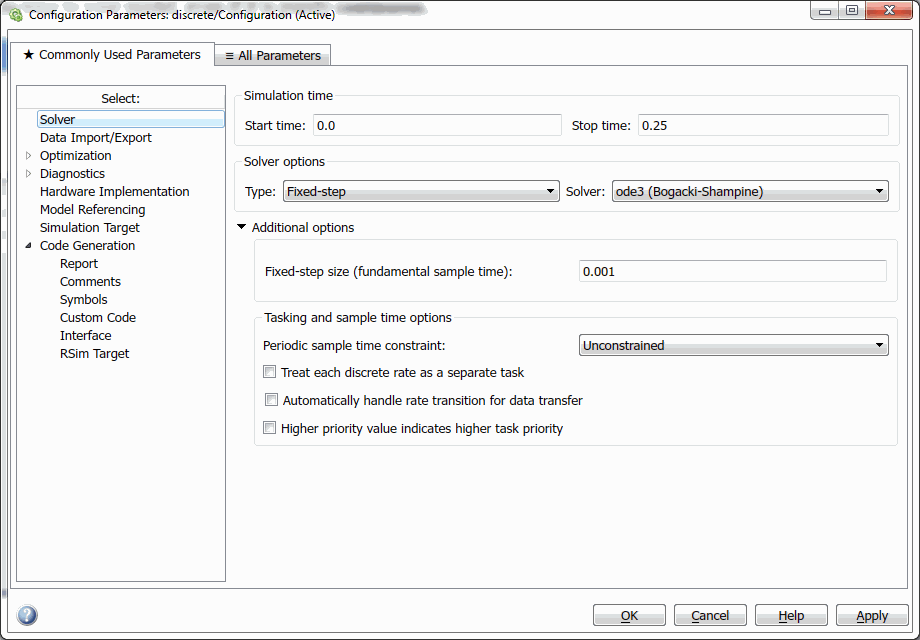
You can choose either Variable-step or Fixed-step solvers in MATLAB/Simulink, under Simulation → Configuration Parameters → Solver → Type. The choice will affect the model code that is generated from Code Generation, in particular to how sample times are handled. This is important to Adams since Adams will be integrating the model, not MATLAB/Code Generation. In this regard, the Variable-step integrator is recommended since Adams Solver uses mainly variable-step integrators, and this will ensure the outputs and states are computed properly. If you would still like to use a Fixed-step integrator setting, the model should have at least one continuous state to produce the code for Adams that will handle the sample times properly. For example, if you have a discrete-only model, add a dummy continuous block (for example, integrator) to the model.
Tip: | ■To look for differences in sample times between Fixed-Step and Variable-step integrators settings, look for the function ssIsSampleHit(), which handles evaluation of code at sample times. ■As a MATLAB requirement, an Code Generation S-Function must have the same type of integrator setting as the model that will use it (that is, both Fixed-step, or both Variable-step). |
Exporting Parameters in Simulink/Code Generation Models to Adams
You can export specific parameters from the Simulink/Code Generation model in order to fine-tune the controller, or conduct design-of-experiments on the External System Library (ESL) without rebuilding the model.
For the block diagram in the example below, the process of exporting the parameters is as follows:
The controller for the antenna model will be used to illustrate this process. This file can be found in install_dir/controls/example/antenna/continuous.mdl. The parameters to be changed are 1040 in Transfer Fcn and 950 in Transfer Fcn1.

Step 1 - Define the parameters in MATLAB workspace
In the MATLAB workspace, issue the following:
■Kp = 1040
■Kv = 950
These two MATLAB variables can be accessed from the Simulink model.
Step 2 - Reference the Kp and Kv in the Simulink model
1. Double-click the Transfer Fcn block. Notice that the numerator is hard-wired with a value of 1040.
2. In the Numerator text box, enter Kp:
3. Select OK.
4. Double-click the Transfer Fcn1 block.
5. In the Numerator text box, enter Kv.
The parameterized Simulink model now looks like this:
Step 3 - Define the proper storage class for parameter export
1. In the Simulink model window, from the Tools menu, point to Code Generation, and then select Options.
2. In the Configuration Parameters window that opens, select Optimization Tab.
3. Under Signals and Parameters, select Inline parameters.
4. Select Configure.
5. Highlight Kp and Kv and select Add to Table.
6. Verify that Storage class is set to SimulinkGlobal(Auto).
7. Select OK to apply the changes and close the Model Parameters Configuration window.
8. In the Configuration Parameters window, select the Code Generation tab.
Here, you generate the C-code and External System Library of the Simulink model. For details on code generation for Adams Controls, refer to the Learning Adams Controls with Control System Import chapter in Getting Started Using Adams Controls.
After the code is generated, the following code appears in continuous_rsim_cg/continuous.h.
/* Parameters (auto storage) */
struct Parameters {
real_T Kp; /* Variable: Kp
* '<Root>/Transfer Fcn'
*/
real_T Kv; /* Variable: Kv
* '<Root>/Transfer Fcn1'
*/
};
extern Parameters rtP; /* parameters */
…and in continuous_rsim_cg/continuous_data.c:
/* Block parameters (auto storage) */
Parameters rtP = {
1040.0, /* Kp : '<Root>/Transfer Fcn'
*/
950.0 /* Kv : '<Root>/Transfer Fcn1'
*/
};
Adams Controls wrapper code (adams.tlc) recognizes this structure and will generate Adams design variables for these parameters. When entering values for these Adams design variables, these are propagated to the Simulink/Code Generation parameters via the arguments to Adams GSE.
Step 4 - Create Code Generation-GSE with the tunable parameters exposed in Adams View
1. Create ESL as described in Learning Adams Controls with Controls System Import.
2. Once the GSE is created, open the Database Navigator and expand the GSE to examine its children - you should see that the design variables Kp and Kv are created. The default values are 1040.0 and 950.0 as defined in the Simulink model. Those design variables can be changed to study the effects on ESL.
Using Control System Import with MATLAB/Simulink/RTW on Windows and Adams Controls on Linux
The process of transporting RTW code from one platform to another is as follows:
Step 1 - Create MATLAB tree on Linux to build RTW library
You need to emulate the Windows MATLAB file structure (tree) on your Linux machine to build the RTW library.
1. Create a directory such as, home/rtwuser/cross.
2. Copy the following directories from the Windows MATLAB installation to the home/rtwuser/cross directory on your Linux machine:
■simulink/include
■extern/include
■rtw/c/rsim
■rtw/c/libsrc
■rtw/c/src
■rtw/c/tools
■rtw/c/tlc
Note: | Your make utility and compiler may be sensitive to DOS/Linux end-of-line character differences. Therefore, we recommend that you run a dos2Linux file conversion utility to ensure your files have a Linux end-of-line. |
Step 2 - Create makefile and C-code template on Linux
1. Set the environment variable MATLAB_ROOT to /home/rtwuser/cross.
2. In the file, /home/rtwuser/cross/rtw/c/rsim/rsim_Linux.tmf, change the following:
■MATLAB_ROOT = |>MATLAB_ROOT<|
to
MATLAB_ROOT = /home/rtwuser/cross
■COMPUTER = |>COMPUTER<|
to
COMPUTER = <MATLAB_computer_name>
where <MATLAB_computer_name> is the name returned by the MATLAB “computer” command (for example, GLNX86). There should be no white space at the end of any line you modified.
This will instruct the template makefile to use /home/rtwuser/cross as your MATLAB tree, and to build on a Linux machine.
3. Create the Adams target in your working directory (in this example, /home/rtwuser/workbench).
Step 3 - Generate C-code and makefile
Here, assume that the working directory on Windows is C:/pcbench, the location of the Simulink model. We assume that the working directory on Linux is /home/rtwuser/workbench/.
1. Copy the modified files, rsim_Linux.tmf, rsim.tlc, and adams.tlc, from /home/rtwuser/workbench/ on Linux to C:/pcbench on Windows.
2. Launch MATLAB from C:/pcbench. Open the Simulink model file. On the RTW Page, change the template makefile to rsim_Linux.tmf.
3. Select Build.
The RTW generates code and a makefile will display, but the executable will not build. You will see a subdirectory called model_rsim_rtw in your C:/pcbench directory.
4. Copy all files in the build directory on Windows (C:/pcbench/model_rsim_rtw) to the working directory on Linux (/home/rtwuser/workbench).
You may need to run a dos2Linux utility against the generated code to conform to Linux end-of-line character standards.
Step 4 - Build RTW dll
1. Enter make -f model.mk in /home/rtwuser/workbench.
2. If there is build failure, you will see error messages. Check to see if there are any Linux end-of-line symbols in the makefile (in the build directory), header files, and source code files in /home/rtwuser/cross.
Now you have the library you require for the Linux platform. Continue with the control system import procedure described in Getting Started Using Adams Controls.
Using Control System Import with MATLAB/Simulink/RTW and Adams Controls on Two Windows Machines
Note: | This procedure applies if you have Adams Controls installed on one Windows machine and MATLAB/Simulink/RTW installed on another Windows machine. |
To import your Simulink model to Adams Controls using RTW:
1. Create a new directory on the machine where Adams Controls is installed, for example, c:/pcbench.
2. Set the MATLAB_ROOT variable in a DOS shell to point to this new directory. For example, enter:
set MATLAB_ROOT=C:/pcbench/
3. Copy the following directories from the MATLAB machine to the directory you just created on the Adams Controls machine:
■simulink/include
■extern/include
■rtw/c/rsim
■rtw/c/libsrc
■rtw/c/src
■rtw/c/tools
■rtw/c/tlc
4. In the Adams working directory (on the Adams Controls machine), run <adams_install_dir>/controls/utils/process.py to create the RTW target for Adams Controls.
5. Copy all of the .tmf and .tlc files from the working directory to the directory on the MATLAB machine where the Simulink model resides.
6. Create the External System Library of the Simulink model on the RTW machine. For specific instructions, see About Control System Import.
7. Copy the created ESL to the working directory on the Adams Controls machine.
The code generation of the Simulink model now exists on both machines.
8. On the machine where Adams Controls is installed, create the GSE with Control System Import and run the simulation (see About Control System Import).
Using Control System Import with S-Functions
The following outlines the general steps to generate an External System Library for Control System Import. For a detailed example, see the Getting Started Using Adams Controls tutorial.
S-Function Support with Source Code
To generate an ESL using an S-Function from source code:
1. Create an S-Function written in C (for example, by using the S-Function Target in Real-Time Workshop (RTW)).
2. Create Simulink model using S-Function from step 1. It must have the same integrator type (Fixed-Step vs. Variable-Step) that was specified in step 1.
3. Generate ESL via RTW using Adams Controls-modified RSIM target (all supporting files for S-Function must be made available, for example, MEX file for S-Function sfunctionname_sf.mexw32 and other source code)
S-Function Support without Source Code
To generate an ESL using S-Function with no S-Function source code:
1. Create an S-Function using S-Function target in the same manner as in steps 1 for "S-Function Support with Source Code".
2. Use Adams Controls setup_rtw_for_adams script to generate Adams Controls-modified RSIM target.
3. Modify model with S-Function to choose RSIM target from step 2 and build S-Function again - this will create an object file that can be used in later steps to build the Adams Controls ESL from RTW.
4. Provide the following when distributing the model to the person who will make the Adams Controls ESL from RTW:
sfunctionname_sf.mexw32
sfunctionname_sf.h
sfunctionname_sfcn_rtw/sfunctionname_sf.h
sfunctionname_sfcn_rtw/sfunctionname_mid.h
sfunctionname_sfcn_rtw/sfunctionname_sid.h
sfunctionname_sfcn_rtw/sfunctionname_sf_private.h
sfunctionname_sfcn_rtw/sfunctionname_sf_types.h
sfunctionname_sfcn_rtw/sfunctionname.mk
sfunctionname_sfcn_rtw/sfunctionname_sf_data.c (if applicable)
modelname_rsim_rtw/sfunctionname_sf.obj
modelname.mdl
5. At the receiver's end, using the files from Step 4, retain the directory structure and place the object file in the directory of the new model's name, for example, "newmodelname_rsim_rtw/sfunctionname_sf.obj"
6. Put the S-Function block in modelname.mdl within the new Simulink model (for example, newmodelname.mdl").
7. Build the ESL using the Adams Controls-modified RSIM target.
Limitations:
If your S-function depends on other modules, this method may fail. You may have to manually add the dependent modules to the S-function by using the following command:
set_param('Sfunction_blockpath','SFunctionModules','file1 file2 file3')
Where:
■'Sfunction_blockpath' is the path of the Sfunction block.
■'file1', 'file2' and so on are the names of the dependent files.
These details can be found also written for another example here:
■How do I build my model that contains an RTW generated S-function block if I do not have the source code?
■How do I build my model containing a C-MEX S-function if I don't have the S-function C source file using Real-Time Workshop?
The overriding rules for working with MATLAB/Simulink/Real-Time Workshop must be followed in use of S-Functions. Please consult Mathworks and their documentation for more details.
Parameterizing S-Functions for Adams
To parameterize an S-Function for Adams, when building the S-Function block using an S-Function target, you must:
1. Build the S-Function using the S-Function target in RTW and choose the parameters to be Global (tunable) Parameters - (that is, Inline, and then choose exceptions -- just as you would for an Adams ESL)
2. Build the ESL using the Adams Controls-modified RSIM target and again choose the same parameters to be Global (tunable) Parameters.
The parameters can be generally found in the "_data.c" files, for example, "sfunctionname_sf_data.c" and "ESL_model_name_data.c" when this is done properly.
For more details on these steps, see the Learning Adams Controls with Control System Import from MATLAB with S-Functions.
Sample Time Setting of Simulink Source Blocks for Adams Controls Target of RTW
In Simulink, some blocks in the source library have a parameter Sample Time, which is the interval at which those block are sampled. Setting sample time in your Simulink/RTW model can change the behavior of the system, and you should take care to select this. If the Sample Time is zero, the blocks can be sampled at any time. In real-time applications, or when the simulation is based on explicit and fixed step-size integration, a nonzero setting of Sample Time makes sense because it controls the progression of the simulation to guarantee accuracy. Adams Solver integrators usually maintain accuracy with variable-step integrator, error controls, and step-size settings (for example, HMAX), which is also true when solving the Adams Controls External System Library (ESL). Thus, the sample rate of continuous states depends on the integrator settings. At the same time, the sample rate for the blocks in the ESL is maintained with internal calls to GSE_SAMP to compute non-zero sample times, and GSE_UPDATE to call the sampled blocks. Therefore, you may want to set the sample time to zero to let Adams Solver sample the block as needed (that is, continuous) instead of at a specified sample rate. You can confirm the sample rates by looking at the RTW source code generated for the Simulink model, for example:
Model_rsim_rtw/Model.c:
…
/* Function to initialize sample times */
void MdlInitializeSampleTimes(void)
{
/* task periods */
ssSetSampleTime(rtS, 0, 0.0);
ssSetSampleTime(rtS, 1, 0.001);
/* task offsets */
ssSetOffsetTime(rtS, 0, 0.0);
ssSetOffsetTime(rtS, 1, 0.0);
}
Here, there is one non-zero sample time (0.001) which will set the sample rate in GSE_SAMP. You can confirm the blocks that use these sample times by searching for the ssIsSampleHit function in this same file.
Finally, setting the Fixed-step size for Simulink can add a sample time to your model, even if it is purely continuous.
Limitations
The models supported by Adams Controls are firstly limited by those restrictions enforced by MATLAB/Real-Time workshop itself. Please consult the Mathworks documentation for the official limitations, but a summary of these can be found next. In addition, Adams Controls has its own limitations for S-Functions support for ESL creation/use which are also listed.
S-Function Target Limitations
Sample Time Propagation in Generated S-Functions
A generated S-Function block can inherit its sample time from the model in which it is placed if certain criteria are met. Six conditions that govern sample time propagation for S-functions and for the S-function code format are described in Inheriting Sample Times in the Simulink documentation. These conditions also apply to sample times propagated to Model blocks, and are further discussed in Inherited Sample Time for Referenced Models.
Rapid Simulation Target Limitations
Adams Controls uses a modified version of the RSIM (rapid simulation) target, and an S-Function must be written in C or C++ to work with the RSim target. The RSim target does not support noninlined M-file, FORTRAN, or Ada S-functions (inlining means to use an RTW .tlc file to write the code for the S-Function directly in the generated code).
■The RSim target is subject to the following limitations:
■The RSim target does not support algebraic loops.
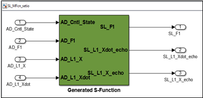
■The RSim target does support MATLAB function blocks, if there is no discrete-time block. However to make this work with discrete-time block, use the below methods.
♦Step 1: Generate the S-Function block from RTW by applying the S-Function Target in Code Generation.
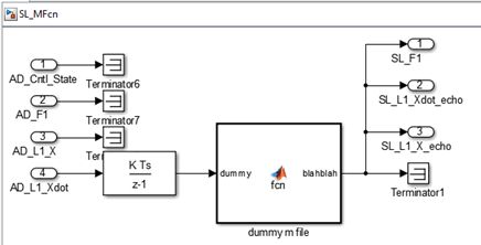
♦Step 2: Create Adams ESL from the Simulink model that contains the S-Function block generated in Step 1.
■The RSim target does not support the transport delay block. However to make this work, use the similar method mentioned in the discrete-time block.
■The RSim target does not support noninlined M-file, FORTRAN, or Ada S-functions.
■If an RSim build includes referenced models (by using Model blocks), these models must be set up to use fixed-step solvers for code to be generated for them. The top model, however, can use a variable-step solver as long as all blocks in the referenced models are discrete (variable-step solver not supported by Adams).
■In certain cases, changing block parameters can result in structural changes to your model that change the model checksum. An example of such a change would be changing the number of delays in a DSP simulation. In such cases, you must regenerate the code for the model.
Adams Controls Limitations
1. RSIM Target
a. Models need to have only one output value per outport.
b. Solver Type: Variable-step solver setting in MATLAB recommended; otherwise, Fixed-step models with no continuous states need to add a continuous block (for example, a dummy integrator block)
c. Inputs and outputs (ports) must be double variable type (that is, "real_T" in RTW code)
d. Variable-time steps for a variable-step integrator are not supported.
2. RSIM and S-Function Targets
a. Parameters must be double type (that is, "real_T" in RTW code) (From SimulinkGlobal(Auto) storage class)
b. Target Language must be in C
Choice of Solver Type: S-Function setting for Solver Type must match setting in the model where it is used. Variable-step solver setting in MATLAB recommended; otherwise, Fixed-step models with no continuous states need to add a continuous block (for example, a dummy integrator block)
c. Blocks:
Discrete Pulse Generator: The discrete pulse generator must be time-based, not sample based.
d. Misc
Must have at least one input and one output for the model, even if it is a dummy (for example, use terminator block to import/outport).