Anti-Roll Bar
Anti-Roll bars connect the left and right suspension systems and are used to increase the roll stiffness, which reduces chassis roll angle.
Anti-Roll bars will be modeled using three different methods:
■Simple - Two rigid parts are connected via a revolute joint and torsional spring. The simple method is fast and efficient when the profile can be represented as a straight line.
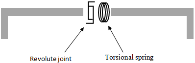
Figure 6 Simple Method Anti-Roll Bar
■Beam - Series of rigid bodies connected by beam forces. The beam element model is a realistic representation of the physical system so the model does not need to be adjusted to get the correct roll rate.
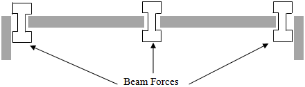
Figure 7 Beam Method Anti-Roll Bar
■FE Part - FE part is used to create anti-roll bar. FE part of type single can be used to represent the anti-roll bar.
The beam and FE Part methods are especially advantageous when modelling anti-roll bars with more complex geometric shapes. Users may choose these options when greater fidelity is desired. The simple anti-roll bar can be used when detailed geometry is not available or when trying to minimize CPU time.
Note: | ■If continuous option is not selected during creation of the anti-roll bar, then in the case of simple method no revolute joint or torsional spring is created. For beam method, the central part will be split into left and right parts and there will be no beam force between them. Use this method if you plan to connect your anti-roll bar parts with other forces/constraints. For example, an active anti-roll bar design would need additional forces/constraints acting on the left and right anti-roll bar parts. ■Continuous option is not supported for FE Part method. Creating left/right symmetric FE parts will create two separate FE Parts with no connection between them. ■Single type anti-roll bar creates a continuous profile in case of beam and FE Part method. |
Creating or Modifying an Anti-Roll Bar
In Standard Interface, to modify an Anti-Roll Bar:
1. From the Adjust menu and then select Anti-Roll Bar.
2. Press F1 and then follow the instructions in the dialog box help for Create/Modify Anti-Roll Bar.
3. Select OK.
In Template Builder, to create or modify an Anti-Roll Bar:
1. From the Build menu, point to Anti-Roll Bar, and then select New/Modify.
2. Press F1 and then follow the instructions in the dialog box help for Create/Modify Anti-Roll Bar.
3. Select OK.
Anti-Roll Bar Profile Definition
Your Anti-Roll Bar profile can be defined using three methods:
Table/Location
A location table can be used to define the profile of the anti-roll bar. You can directly enter the locations into the table, without the need to manually create hardpoints or construction frames to define the profile of anti-roll bar. If desired (for example, connection points), users can specify a new or existing hardpoint or construction frame from table itself. Some of the key features of the table are demonstrated below.
■Create Hardpoint: Hardpoint can be created two ways, as shown below.
Features: | Graphical Representation |
|---|---|
Right click on the row and select Create as New Hardpoint. | 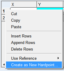 |
Right click on cell of the coordinate reference column and select Create. | 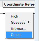 |
The location from the corresponding row gets auto populated in the hardpoint creation dialog box. After creation of a new hardpoint, it gets referenced in the coordinate reference column cell.
■Insert rows: This will insert rows equal to the selected rows before the top selected row.
■Append rows: This will insert rows equal to the selected rows after the bottom selected row.
■Delete rows: This will delete the selected rows.
■Use reference: You can refer to a hardpoint or construction frame by picking, guessing or browsing.
■Modify (after a coordinated reference has been selected): Modify the referenced hardpoint or construction frame.
■Clear Reference (after a coordinated reference has been selected): Remove the reference to a hardpoint or construction frame, without clearing the location values.
Outline
You can use an existing outline to specify the anti-roll bar centerline. For left/right symmetry type with continuous option selected, the Y co-ordinate of the last point of the outline should be set to zero.
B-Spline
You can use an existing B-Spline to specify the anti-roll bar centerline. For left/right type with continuous option selected, the Y co-ordinate of the last point of the B-Spline should be set to zero.