Setting up model for Adams Car SDI full vehicle analyses
In this section, more detailed information is given about how to setup the powertrain/driveline model for an Adams Car full vehicle SDI analysis, including a Quasi-Static setup. The demo model in the shared Adams Driveline database, JEEP_RWD_SDI.asy, will serve as an example. The following topics will be discussed:
Powertrain/driveline communicators in SDI testrig
In order to communicate with the Adams Car full vehicle SDI testrig, a number of input communicators has to be fed to it. In the section “Working with Communicators”, all input communicators to the SDI testrig are listed, but in Table 1 only those that are related to the powertrain/driveline are presented. The last column shows the communicators which are the minimum requirement for running Driving Machine closed loop events (referred to as “machine” controlled events). The other communicators are only needed for the Driving Machine SmartDriver events. In these events a low degree of freedom (DOF) vehicle model pre-calculates a speed trajectory profile based on the vehicle limit values. The low DOF vehicle model needs additional information about the full vehicle and powertrain properties.
Table 1 SDI testrig powertrain/driveline communicators
The input communciator: | Belongs to the class: | From minor role: | Receives: | Min. requirement for Driving machine closed loop events: |
|---|---|---|---|---|
cis_crankshaft_ratio | parameter_real | any | ||
cis_diff_ratio | parameter_real | any | Real parameter variable for final drive ratio, from the powertrain subsystem. | |
cis_drive_torque_bias_front | parameter_real | any | ||
cis_engine_idle_rpm | parameter_real | any | ||
cis_engine_revlimit_rpm | parameter_real | any | ||
cis_engine_rpm | solver_variable | any | Adams Solver variable for engine revolute speed, in rotations per minute, from the powertrain subsystem. | yes |
cis_engine_speed | solver_variable | any | Adams Solver variable for engine revolute speed, in radians per second, from the powertrain subsystem. | yes |
cis_engine_map | spline | any | Engine torque map from powertrain subsystem. | yes |
cis_max_engine_braking_torque | solver_variable | any | Engine torque at zero throttle | yes |
cis_max_engine_driving_torque | solver_variable | any | Engine torque at full throttle (100%) | yes |
cis_max_engine_speed | parameter_real | any | Output from powertrain subsystem (maximum engine rpm value). | yes |
cis_max_gears | parameter_integer | any | Output from powertrain (maximum number of allowed gears). | yes |
cis_min_engine_speed | parameter_real | any | Output from powertrain subsystem (minimum engine rpm value, used for shifting strategy). | yes |
cis_transmission_efficiency | parameter_real | any | ||
cis_transmission_input_omega | solver_variable | any | The transmission input engine variable from the powertrain template. Expressed in radians per second | yes |
cis_transmission_spline | spline | any | Spline for transmission gears (output from powertrain: reduction ratios for every gear). |
General information about Quasi-Static setup analysis in Adams Car
The objectives of a Quasi-Static setup analysis are to calculate the initial throttle demand and wheel speed of the driven wheels. The throttle demand should result in an engine torque that balances the different vehicle resistance forces (tire rolling resistance, aerodynamic drag, and so on.) at the specified initial vehicle speed and gear position.
In the dynamic simulation, the engine torque is calculated from a three-dimensional engine map spline where the two independent parameters are throttle demand and engine speed. The throttle demand signal is received from the Driving Machine while the engine speed can be measured in the engine model by using standard Adams Solver expressions. The engine speed can for example be evaluated by using the WZ function when a rotating crank shaft part exists in the engine model or with the VARVAL function when the engine speed is calculated in a state variable.
In the Quasi-Static setup simulation, the throttle demand is instead calculated by using a differential equation and the engine speed is calculated from the quasi-static wheel speeds and the different known ratios in the driveline (gear ratio, differential ratio, and so on.). With these two quantities calculated, the static engine torque can be derived by using the very same engine map spline that is used in the dynamic simulation.
So, how is the Quasi-Static steady state wheel speed calculated? During the static equilibrium analysis, the wheels are prevented from rotating relative to ground by using perpendicular primitive joints and the body is constrained to ground with an inline primitive joint. The throttle demand differential equation and the tire general state equations strives to zero out the reaction torque/force in these joints (since there should be no accelerations for a constant velocity). The result is that the drive torque gets balanced by the longitudinal tire forces which are dependent on the longitudinal wheel slips. Once the slip is calculated by the static solver and the initial velocity of the vehicle speed is known, the wheel speed can be evaluated. During the static solver iterations, the only unknown states are the wheel longitudinal slips of the driven wheels. All other states such as wheel speeds, engine speed, engine torque and throttle demand are therefore directly or indirectly dependent on these slip values.
Since wheel speeds can not be accessed directly in the static equilibrium analysis by using standard Adams Solver expressions, these speed values can be evaluated by using the Adams Solver VARSUB subroutine, VAR1004. Besides the information about I and J markers, the routine needs also information about which tire (slip) to evaluate. The call to the subroutine is done in the brake templates in the Adams Car and Adams Driveline shared database models. In the Adams Driveline SDI model, JEEP_RWD_SDI.asy, the wheel speeds are also published to other subsystems via output communicators. More information about the implementation done in that shared model can be found in the section Implementation in shared Adams Driveline SDI vehicle model.”
Preparing Adams Driveline model for Quasi-Static setup
The approach to support Quasi-Static setup for an Adams Driveline model that uses an ac_dyno element to apply the engine torque, is to modify the state variable rpm_input. This state variable calculates the engine speed in revolutions per minute and is normally used when calculating the engine torque in a dynamic analysis. But if the requirements below are satisfied, the torque calculations also become valid in Quasi-Static setup equilibrium analyses.
There are in total three requirements that need to be fulfilled in order to support Quasi-Static setup analysis when using an ac_dyno to drive the engine:
1. There can only be one active ac_dyno present in the assembly
2. The ac_dyno element is required to be setup as per below:
■Dyno type = Torque
■Function type = Throttle Demand
3. An output communicator with the matching name “engine_rpm_sse” (engine rpm steady state equilibrium) has to exist in the model, as noted below.
Table 2 Required output communicator for the ac_dyno
The input communciator: | Belongs to the class: | From minor role: | Receives: | Transmitts: |
|---|---|---|---|---|
cos_engine_rpm_sse | solver_variable | any | engine_rpm_sse | Adams Solver variable for (back) calculated engine speed, in revolutions per minute, in the Quasi-Static (steady state) equilibrium phase |
The output communicator above has to point to a state variable which calculates the engine speed during the quasi-static equilibrium analysis. The engine speed during this analysis type can be calculated as in the equation below:
engine_speed = total_drive_line_ratio * wheel_speed (1)
Where the wheel_speed is the Quasi-Static speed of the wheels that can be accessed via a VAR1004 call. The total driveline ratio should be calculated as the ratio of engine speed and wheel speed for the given gear position and it includes all ratios in the model such as gear ratio, differential reduction ratio, etc.
If the requirements above are satisfied, the expression of rpm_input state variable in the ac_dyno element gets automatically adjusted for the Quasi-Static setup analysis, as explained below:
Standard expression of rpm_input state variable:
WZ(ac_dyno.i_marker,ac_dyno.j_marker,ac_dyno.j_marker)*60/(2*PI)
Modified expression of rpm_input state variable to suit a Quasi-Static setup analysis:
(IF(MODE-5:0,1,0)+IF(MODE-6:0,1,0))*
VARVAL(cos_engine_rpm_sse_adams_id)
+
(IF(MODE-4:1,1,0)+IF(MODE-6:0,0,1))*
WZ(ac_dyno.i_marker,ac_dyno.j_marker,ac_dyno.j_marker)*60/(2*PI)
It is only during mode 5 and 6 (static equilibrium and quasi-static equilibrium) that the value from the engine_rpm_sse output communicator is used. For all other simulation modes, the original expression is kept.
When running an Adams Car SDI analysis with a Quasi-Static setup, the following message is shown in the Message Window if the setup of the ac_dyno worked properly:
Setting up rpm_input variable in dyno (name of ac_dyno)
to support Quasi-Static Straight-Line Setup...
Setup of dyno is completed.
If an ac_dyno is not used in the assembly, that is, you have modeled your own engine torque implementation, you are still able to use the Quasi-Static setup capability if the following conventions are applied:
1. The engine torque has to be dependent on throttle demand and engine speed. Throttle demand value of 100 should produce maximum engine torque for the specific engine speed.
2. Engine speed expression used in the engine torque calculation needs to be setup in a way that it is still valid in the Quasi-Static setup analysis. The user can use the modified rpm_input state variable expression shown previously as an example. A recommendation is also to use the wheel speeds that are calculated in the way that is done in the shared Adams Driveline brake system template.
Lastly, it is required that the different powertrain/driveline components properly inherit the calculated Quasi-Static wheel speeds in the initial velocity analysis. This can be accomplished by correctly setting up the initial condition motions. More information can be found in the section “Setting up Initial Condition Motions Activity Analyses” and in section “Setting up Initial-Velocity Analyses.”
Implementation in shared Adams Driveline SDI vehicle model
In the Adams Driveline shared database, the full vehicle assembly JEEP_RWD_SDI.asy is prepared for Adams Car SDI analysis. The used engine, driveline, gearbox and brake subsystems and templates in that assembly are listed below:
Table 3 Systems in JEEP_RWD_SDI.asy assembly which are involved in the Powertrain/Driveline SDI testrig and Quasi-Static setup communication.
System | Subsystem file: | Template file: |
|---|---|---|
Brake system | JEEP_brake_system.sub | _brake_4Wdisk_adriveline.tpl |
Driveline | RWD_driveline.sub | _RWD_driveline.tpl |
Gearbox | gearbox_longitudinal_syncro.sub | _gearbox_longitudinal_syncro.tpl |
Engine | engine_02.sub | _engine.tpl |
In the Figure 1 an overview of these systems in the assembly is shown. The powertrain/driveline related communication from and to the full vehicle SDI testrig and the internal communication used for the Quasi-Static setup is presented as well. The green “In” arrows shows communicators to a certain subsystem while the blue “Out” arrows lists the information sent from the subsystem.
Figure 1 Overview of powertrain/driveline in assembly JEEP_RWD_SDI.asy
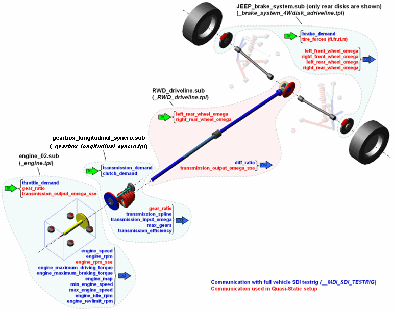
Most of the SDI testrig input communicators listed in table 1 are matched in this configuration and the required output communicator “engine_rpm_sse” for the Quasi-Static setup is here located in the engine system. The total_driveline_ratio in equation [2] is here divided into two parameters, gear_ratio and diff_ratio, and can be expressed as below:
total_driveline_ratio = gear_ratio [gear position] * diff_ratio (2)
Next, the powertrain/driveline related communication between the different systems and the parameters such as those above are described in more detail.
Brake system
Starting from the brake system, calls are made to the VAR1004 subroutine that calculates the wheel speeds values during the Quasi-Static setup equilibrium phase. These speed values are then published to other subsystem via the output communicators listed below:
■left_front_wheel_omega
■right_front_wheel_omega
■left_rear_wheel_omega
■right_rear_wheel_omega
The inputs to the brake system are mainly brake_demand (received from the SDI testrig) and the tire forces (from the wheel templates). The id’s of the tire forces are passed as parameters in the VAR1004 calls, see Table 6.
Figure 2 Brake template: _brake_system4W_disk_acdriveline.tpl
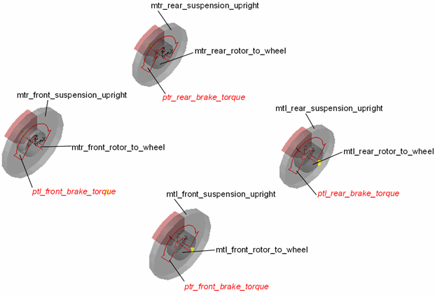
This template originates from the shared Adams Car template _brake_system_4Wdisk.tpl. The only difference is that the Adams Driveline version publishes the wheel speeds.
More complete brake system information about entities related to SDI testrig and Quasi-Static setup are shown in the tables below:
Table 4 Input communicators in brake system which are related to SDI testrig and Quasi-Static setup
The input communicator: | Belongs to class: | Minor role: | Matching name: |
|---|---|---|---|
cis_brake_demand | solver_variable | any | brake_demand |
cil_rear_tire_force | force | rear | tire_force |
cil_front_tire_force | force | front | tire_force |
Table 5 Output communicators in brake system which are related to SDI testrig and Quasi-Static setup
The output communicator: | Belongs to class: | Minor role: | Matching name: | Points to entity: |
|---|---|---|---|---|
cos_left_rear_wheel_omega | solver_variable | any | left_rear_wheel_omega | left_rear_wheel_omega |
cos_right_rear_wheel_omega | solver_variable | any | right_rear_wheel_omega | right_rear_wheel_omega |
cos_left_front_wheel_omega | solver_variable | any | left_front_wheel_omega | left_front_wheel_omega |
cos_right_front_wheel_omega | solver_variable | any | right_front_wheel_omega | right_front_wheel_omega |
Table 6 States variables in brake system which are related to SDI testrig and Quasi-Static setup
The state variable: | Subroutine parameter: | Parameter value: |
|---|---|---|
left_front_wheel_omega | par1 par2 par3 par4 par5 | 1004 (mtl_front_rotor_to_wheel.ptl_actuator_i_1.adams_id) (mtl_front_suspension_upright.ptl_actuator_j_1.adams_id) (mtl_front_suspension_upright.ptl_actuator_j_1.adams_id) (cil_front_tire_force_adams_id) |
right_front_wheel_omega | par1 par2 par3 par4 par5 | 1004 (mtr_front_rotor_to_wheel.ptr_actuator_i_1.adams_id) (mtr_front_suspension_upright.ptr_actuator_j_1.adams_id) (mtr_front_suspension_upright.ptr_actuator_j_1.adams_id) (cir_front_tire_force_adams_id) |
left_rear_wheel_omega | par1 par2 par3 par4 par5 | 1004 (mtl_rear_rotor_to_wheel.ptl_actuator_i_2.adams_id) (mtl_rear_suspension_upright.ptl_actuator_j_2.adams_id) (mtl_rear_suspension_upright.ptl_actuator_j_2.adams_id) (cil_rear_tire_force_adams_id) |
right_rear_wheel_omega | par1 par2 par3 par4 par5 | 1004 (mtr_rear_rotor_to_wheel.ptr_actuator_i_2.adams_id) (mtr_rear_suspension_upright.ptr_actuator_j_2.adams_id) (mtr_rear_suspension_upright.ptr_actuator_j_2.adams_id) (cir_rear_tire_force_adams_id) |
Driveline
This rear-wheel drive model uses the rear wheel speeds from the brake system to calculate the transmission output speed to be used in the Quasi-Static setup analysis phase, as per the equation below:
transmission_output_omega_sse = (left_rear_wheel_omega+right_rear_wheel_omega)/2*diff_ratio (3)
The transmission output shaft speed is then communicated to other subsystems (used in the engine system in this case). Another output from this system is the diff_ratio which is used by SDI testrig. The diff_ratio parameter value is taken from the reduction gear ratio set in the differential gear arrangement; see Figure 3.
Figure 3 Driveline template: _RWD_driveline.tpl
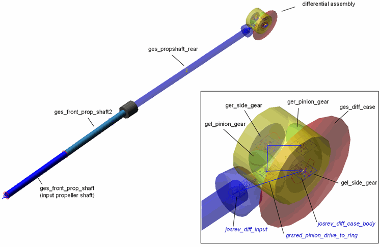
Note that the transmission output speed (that is, the speed of the input propeller shaft) in equation [3] is not used in any dynamic analysis, where the speed is instead determined by dynamic torque from the gearbox, resistance torque from the differential gear parts, inertia and compliance effects of the propeller shaft, different lash effects, and so on.
More complete driveline information about entities related to SDI testrig and Quasi-Static setup are shown in the tables below:
Table 7 Input communicators in driveline system which are related to SDI testrig and Quasi-Static setup
The input communicator: | Belongs to class: | Minor role: | Matching name: |
|---|---|---|---|
cis_left_rear_wheel_omega | solver_variable | any | left_rear_wheel_omega |
cis_right_rear_wheel_omega | solver_variable | any | right_rear_wheel_omega |
Table 8 Output communicators in driveline system which are related to SDI testrig and Quasi-Static setup
The output communicator: | Belongs to class: | Minor role: | Matching name: | Points to entity: |
|---|---|---|---|---|
cos_diff_ratio | parameter_real | inherit | diff_ratio | grsred_pinion_drive_to_ring.reduction_ratio |
cos_transmission_output_omega_sse | solver_variable | inherit | transmission_output_omega_sse | VAR_transmission_output_omega_sse |
Table 9 State variables in driveline system which are related to SDI testrig and Quasi-Static setup
The state variable: | Function: |
|---|---|
VAR_transmission_output_omega_sse | (VARVAL(cis_left_rear_wheel_omega_adams_id)+ VARVAL(cis_right_rear_wheel_omega_adams_id))/2*grsred_pinion_drive_to_ring.reduction_ratio |
Table 10 Reduction Gears in the driveline system which are related to SDI testrig and Quasi-Static setup
The reduction gear: | Joint1: | Joint2: | Default ratio: |
|---|---|---|---|
grsred_pinion_drive_to_ring | josrev_diff_input | josrev_diff_case_body | 2.6 |
Gearbox
The gearbox model uses the transmission_demand and clutch_demand from the SDI testrig and publishes to the testrig the gear ratios for all gear positions (transmission_spline), highest gear position number (max_gears) and a scalar value between 0 and 1 which represent a transmission efficiency value. This value is used in (Driving Machine) SmartDriver events. The gearbox input shaft speed (transmission_input_omega) is published to the SDI testrig as well.
Figure 4 Gearbox template: _gearbox_longitudinal.tpl
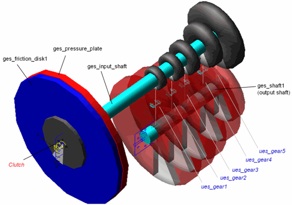
Since this gearbox can not switch gears during the simulation, the transmission_demand information is only used to calculate the gear ratio value (gear_ratio) for the initial gear position; see expression in Table 15. This value is used in the Quasi-Static setup analysis by the engine subsystem.
More complete gearbox information about entities related to SDI testrig and Quasi-Static setup are shown in the tables below:
Table 11 Input communicators in gearbox system which are related to SDI testrig and Quasi-Static setup
The input communicator: | Belongs to class: | Minor role: | Matching name: |
|---|---|---|---|
cis_clutch_demand_1 | solver_variable | inherent | clutch_demand |
cis_clutch_demand_2 | solver_variable | inherent | clutch_demand |
cis_transmission_demand | solver_variable | inherit | transmission_demand |
Table 12 Input communicators in gearbox system which are related to SDI testrig and Quasi-Static setup
The output communicator: | Belongs to class: | Minor role: | Matching name: | Points to entity: |
|---|---|---|---|---|
cos_max_gears | parameter_integer | inherit | max_gears | pvs_max_gears |
cos_transmission_efficiency | parameter_real | inherit | transmission_efficiency | pvs_transmission_efficiency |
cos_transmission_spline | spline | inherit | transmission_spline | gear_ratio_spline |
cos_transmission_input_omega | solver_variable | inherit | transmission_input_omega | VAR_transmission_input_omega |
cos_gear_ratio | parameter_real | inherit | gear_ratio | gear_ratio |
Table 13 State variables in gearbox system which are related to SDI testrig and Quasi-Static setup
The state variable: | Function: |
|---|---|
VAR_transmission_input_omega | WZ(ges_input_shaft.jxs_joint_i_9,mts_body.jxs_joint_j_9, mts_body.jxs_joint_j_9) |
Table 14 Splines in gearbox system which are related to SDI testrig and Quasi-Static setup
The spline: | Spline values: |
|---|---|
gear_ratio_spline | -3.0 (dummy value) 0.0 (ues_gear1.ratio) (ues_gear2.ratio) (ues_gear3.ratio) (ues_gear4.ratio) (ues_gear5.ratio) |
Table 15 Parameter and variables in gearbox system which are related to SDI testrig and Quasi-Static setup
The parameter/variable name: | Type: | Units: | Default value / parameterisation: |
|---|---|---|---|
pvs_max_gears | integer | 5 | |
pvs_transmission_efficiency | real | no_units | 1.0 |
gear_ratio | real | VALAT(gear_ratio_spline.xs, gear_ratio_spline.ys, cis_transmission_demand.object_value.initial_condition) |
Engine
The engine template has in this case the largest portion of the powertrain/driveline related communication with the SDI testrig. The input from the SDI testrig to the engine is the throttle demand (throttle_ demand) while it publishes information different dynamic engine speed and engine torque quantities, as in Figure 5 and Table 16 below. In the Quasi-Static setup analysis, the engine speed is calculated as below:
engine_rpm_sse = gear_ratio * transmission_output_omega_sse (4)
where the gear_ratio parameter value is received from the gearbox subsystem and the Quasi-Static speed of the transmission output shaft (transmission_output_omega_sse) comes from the driveline subsystem.
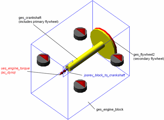
Figure 5 Engine template: _engine.tpl
More complete engine information about entities related to SDI testrig and Quasi-Static setup are shown in the tables below:
Table 16 Input communicators in engine system which are related to SDI testrig and Quasi-Static setup
The input communicator: | Belongs to class: | Minor role: | Matching name: |
|---|---|---|---|
cis_throttle_demand | solver_variable | any | throttle_demand |
cis_gear_ratio | parameter_real | inherit | gear_ratio |
cis_transmission_output_omega_sse | solver_variable | any | transmission_output_omega_sse |
Table 17 Output communicators in engine system which are related to SDI testrig and Quasi-Static setup
The output communicator: | Belongs to class: | Minor role: | Matching name: | Points to entity: |
|---|---|---|---|---|
cos_engine_map | spline | inherit | engine_map | ues_engine_torque.gss_spline |
cos_engine_rpm | solver_variable | inherit | engine_rpm | VAR_ENGINE_RPM |
cos_engine_speed | solver_variable | inherit | engine_speed | VAR_ENGINE_OMEGA |
cos_default_downshift_rpm | parameter_real | inherit | min_engine_speed | pvs_engine_idle_speed |
cos_engine_idle_rpm | parameter_real | inherit | engine_idle_rpm | pvs_engine_idle_speed |
cos_default_upshift_rpm | parameter_real | inherit | max_engine_speed | pvs_engine_rev_limit |
cos_engine_max_rpm | parameter_real | inherit | engine_revlimit_rpm | pvs_engine_rev_limit |
cos_max_engine_braking_torque | solver_variable | inherit | engine_maximum_braking_torque | VAR_max_braking_torque |
cos_max_engine_driving_torque | solver_variable | inherit | engine_maximum_driving_torque | VAR_max_driving_torque |
cos_engine_rpm_sse | solver_variable | inherit | engine_rpm_sse | VAR_ENGINE_RPM_SSE |
Table 18 Ac dyno in the engine system which is related to SDI testrig and Quasi-Static setup
The Dynos: | I Part: | J Part: |
|---|---|---|
ues_engine_torque | ges_crankshaft | ges_engine_block |
Table 19 State variables in engine system which are related to SDI testrig and Quasi-Static setup
The state variable: | Function: |
|---|---|
ues_engine_torque.rpm_input | WZ(ues_engine_torque.i_marker,ues_engine_torque.j_marker,ues_engine_torque.j_marker) *60/(2*PI) |
VAR_ENGINE_RPM | ABS(wz(ges_crankshaft.jxs_joint_i_8,ges_engine_block.jxs_joint_j_8, ges_engine_block.jxs_joint_j_8)*60/(2*PI)) |
VAR_ENGINE_OMEGA | VARVAL(VAR_ENGINE_RPM)*PI/30 |
VAR_ENGINE_RPM_SSE | VARVAL(cis_transmission_output_omega_sse_adams_id)*cis_gear_ratio*30/PI |
VAR_max_braking_torque | AKISPL(MAX(0,VARVAL(ues_engine_torque.rpm_input)),0,ues_engine_torque.gss_spline) |
VAR_max_driving_torque | AKISPL(MAX(0,VARVAL(ues_engine_torque.rpm_input)),1,ues_engine_torque.gss_spline) |
Table 20 Splines in engine system which are related to SDI testrig and Quasi-Static setup
The spline: | Spline values: |
|---|---|
ues_engine_torque.gss_spline | 3D dimensional engine map spline: Input parameter 1: Throttle (0->100) Input parameter2: engine speed (rpm) Output: engine torque |
Table 21 Parameters in engine system which are related to SDI testrig and Quasi-Static setup
The parameter: | Type: | Units: | Default value: |
|---|---|---|---|
pvs_engine_idle_speed | real | no_units | 1000.0 |
pvs_engine_rev_limit | real | no_units | 6000.0 |