Hypoid Gear Forces
This component represents hypoid gear forces. It consists of the following objects:
■A general force featuring the actions and reactions between the ring gear and pinion gear.
■Two differential equations to calculate gear angular error and angular error integral.
Learn about hypoid gear forces:
Creating or Modifying Hypoid Gear Forces
To create or modify hypoid gear forces:
1. From the Driveline Components menu, point to Hypoid Gear Force, and then select New/Modify.
3. Select OK.
About Hypoid Gear Forces
Theoretical Background
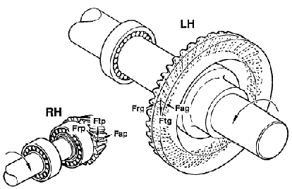
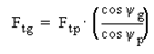
The forces exchanged between ring gear and pinion gear at the mesh point can be evaluated as shown in the following tables.
Front and Rear Axles in Drive Conditions
Axial force: | Separating force: | |
|---|---|---|
PINION |  |  |
GEAR | 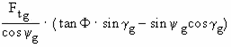 | 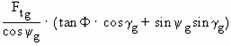 |
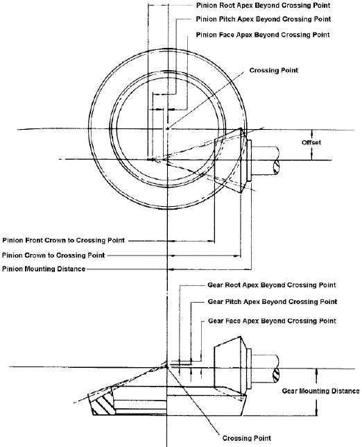
The gear mesh point position can be calculated as:
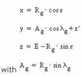
■x, y, z | = Mesh point location |
■  p, p,  g g | = Pinion face, gear root angles |
■  | = Gear offset angle |
■  p, p,  g g | = Pinion and gear offset angles |
■  | = Pressure angle |
■  p, p,  g g | = Pinion and gear spiral angles |
■Ap, Ag | = Pinion and gear mean cone distances |
■E | = Offset of gear and pinion centerlines |
■Rp, Rg | = Pinion and gear mean radius |
■z' | = Gear pitch apex beyond crossing point |
Adams Driveline implements the component with general forces using, as reference, frame markers positioned at the gear mesh point. It calculates the location and orientation of these reference markers into the component using data you provide.
The following figure shows how you must orient reference frames for a correct evaluation of gear forces
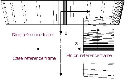 :
:You must create the case reference frame on the intersection of the z-axis of the pinion reference frame and the z-axis of the ring reference frame. Adams Driveline uses the case reference frame to locate the marker at the gear contact point.
In the Template Builder, you can specify the parameters as shown next.
Hypoid Gear Parameters
Parameter: | Description: |
|---|---|
Pinion gear I part | Rigid part modeling the pinion |
Pinion gear J part | Rigid part to which pinion part is connected |
Ring gear I part | Rigid part modeling the ring gear |
Ring gear J part | Rigid part to which ring gear is connected |
Pinion reference frame | At pinion gear joint location, z-axis pointing towards pinion apex |
Ring reference frame | At ring gear joint location, z-axis pointing towards ring apex |
Case reference frame | At crossing point of ring reference frame and pinion reference frame |
Stiffness | Gear forces stiffness |
Damping | Gear forces damping |
Differential location | Front or rear |
Property file | Stores the hypoid gear properties (see Hypoid Gear Example Property File). ■PINION_N_OF_TEETH ■PRESSURE_ANGLE ■PINION_OFFSET ■PINION_MEAN_CONE_DISTANCE ■PINION_PITCH_ANGLE ■PINION_MEAN_SPIRAL_ANGLE ■RING_N_OF_TEETH ■RING_MEAN_CONE_DISTANCE ■RING_PITCH_ANGLE ■RING_MEAN_SPIRAL_ANGLE ■RING_OFFSET_ANGLE ■RING_FACE_WIDTH ■RING_PITCH_APEX |
Example Hypoid Gear-Forces Property File
$--------------------------------------------------MDI_HEADER
[MDI_HEADER]
FILE_TYPE = 'hyp'
FILE_VERSION = 4.0
FILE_FORMAT = 'ASCII'
$--------------------------------------------------UNITS
[UNITS]
LENGTH = 'mm'
ANGLE = 'degrees'
FORCE = 'newton'
MASS = 'kg'
TIME = 'second'
$--------------------------------------------------GEAR_PARAMETERS
[GEAR_PARAMETERS]
PINION_N_OF_TEETH = 133
PRESSURE_ANGLE = 15.633
PINION_OFFSET = 38.1
PINION_MEAN_CONE_DISTANCE = 120.0404
PINION_PITCH_ANGLE = 20.1
PINION_MEAN_SPIRAL_ANGLE = 48.533
RING_N_OF_TEETH = 43
RING_MEAN_CONE_DISTANCE = 102.0572
RING_PITCH_ANGLE = 68.5333
RING_MEAN_SPIRAL_ANGLE = 27.20
RING_OFFSET_ANGLE = 20.0667
RING_FACE_WIDTH = 32.512
RING_PITCH_APEX = 3.556