Component Mode Synthesis
Background
Component mode synthesis is an effective method of evaluating stress. The following topics show how the results of a finite-element (FE) analysis are comparable to theoretical ones
An important issue in machine design is ensuring that the strength of a part’s material exceeds the stress of the loads imposed on it.
The basic stress equation formulas assume that no geometrical irregularities occur in the member under consideration. This is not always true in the practical design of real machines, when changes to the cross-sections of the members are permitted.
Such geometric variations in a machine part modify the stress distribution in the neighborhood of the discontinuities, so that the elementary stress equation no longer describes the correct stress distribution. For example, if you consider the latter on a rectangular plate with a hole in the center, you would find that the stress is highest at the edge of the hole, and that the stress concentration effect is highly dependent on the vicinity of the hole’s edge.
A theoretical stress concentration factor (Kt) is used to relate the maximum stress at the discontinuity to the nominal stress; the factor is defined by the equations.
where Kt is used for normal stress and Kts is used for shear stress.
The nominal stress is usually calculated by the basic stress equations. Meanwhile, the maximum stress (which depends on the geometry of the part or the type of irregularity considered) can be calculated by numerical methods (finite-element analysis (FEA)) or by experimental tests.
Stress Concentration Evaluation
A study on stress and stress concentration evaluation was performed using modern numerical tools. The multi-body approach to the study of flexible parts has been compared to the well-known finite-element model (FEM) method, giving important results about the accuracy of the component mode synthesis method used by multi-body software Adams.
Example: Rectangular Filleted Bar in Bending
This example shows how stress on a reference model is calculated (using the CMS approach), comparing the MB CMS results with finite-element model (FEM) results and analytical ones.
It validates stress recovery from a multi-body analysis in the presence of stress concentration, considering a rectangular plane filleted bar under bending load.
The following figure shows the stress concentration factor (Kt) for the normal stress, plotted against the geometric dimensions of the part. The main test case properties are shown in table below the figure.
Material | Young Modulus (N/m2) | D (m) | d (m) | r (m) | s (m) | M (N m) |
|---|---|---|---|---|---|---|
Steel | 2.1E11 | 5.0E-2 | 3.85E-2 | 2E-3 | 1.0E-2 | 1 |
In this example, Kt= 2.225, so the maximum nominal stress can be analytically evaluated as:

and the maximum normal stress due to the stress concentration is:

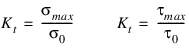
The same problem was studied in a finite-element program (ANSYS 5.4) and a multi-body software (Adams 9.2).
A planar FE model was realized using shell43 elements (7194 elements and 7369 nodes). Then, the model was exported in Adams, creating an MNF with 26 modes (20 normal and 6 static correction modes).
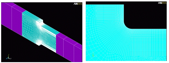
Both FE and MB models were loaded with the same conditions as in the analytical case. The modal coordinate resulting from the MB analysis and the modal stress matrix were used to calculate the nodal stresses.
The results of the comparisons between FEM and MB analysis are shown below:
Stress comparisons (N/m2) |  |  |  |  |  |  |  | Kt |
ANSYS Node 408 | -8.7086E+05 | -4.0686E+04 | 0.0 | 1.4512E+05 | 0.0 | 0.0 | 8.8758E+05 | 2.1922 |
ANSYS Node 4040 | -4.0492E+05 | -0.0094E+04 | 0.0 | -0.00678E+05 | 0.0 | 0.0 | 4.0487E+05 | |
Adams Node 408 | -8.5691E+05 | -3.9986E+04 | 0.0 | 1.4284E+05 | 0.0 | 0.0 | 8.7340E+05 | 2.1640 |
Adams Node 4040 | -4.0375E+05 | -0.0302E+04 | 0.0 | -0.00346E+05 | 0.0 | 0.0 | 4.0360E+05 |