Working with the Adams Flex Toolkit Command Line
Adams Flex Toolkit Command Line
In additional to the GUI, the Adams Flex Toolkit also provides three extra command line tools, which are:
■MNFXFORM - Translating, rotating or mirroring an MNF (MD DB)
■MNFRES - Recovering nodal displacement, velocity or acceleration of a flexible body
■ABQ2NAS - Converts Abaqus input files to MSC Nastran input files
■MNF2MTX - Edit interface node coordinates or generalized mass/stiffness of MNF
To run the Adams Flex toolkit command line from the program menu, enter adams2024_1 -c flextk on Linux systems or adams2024_1 flextk on Windows systems.
Transforming an MNF or an MD DB
In MNF (MD DB), the data are defined with respect to the FE origin. MNFXFORM is a tool to translate, rotate or mirror the MNF (MD DB) with respect to the FE origin. Please be noted that this is different from specifying position and orientation of a flexible body in AView, which only changes how the FE origin is positioned and oriented and could not change how the flexible body is positioned and oriented with respect to the FE origin.
Without this tool, the only way user can change how a flexible body is positioned or oriented with respect to its FE origin is to go back to FE preprocessor to transform the FEA model and generate a new MNF (MD DB).
Some of the benefits this tool provides include:
1. In high speed rotation simulation, the simulation speed can be significantly improved if the rotation axis is aligned with the Z axis of the FE origin. With MNFXFROM, user can easily rotate the flexible body to this configuration.
2. It involves some extra efforts to generate a mirrored copy of an MNF (MD DB) from FEA code. With this tool, this task becomes trivial. Adams Car users whose models often involve symmetrical parts will find this tool is very handy.
MNFXFORM Usage
Following is the usage of the mnfxform command under flextk:
mnfxform <option> <input_flex_file> <output_flex_file> <parameters>
[-offset inc] [-id nid n1 n2 n3 ...]
Following are explanation of the arguments.
Argument: | Description: |
|---|---|
<option> | Specify which transformation to perform. The option should be one of the following: -t for Translation. This transformation needs to input direction and distance in <parameters> -r for Rotation. This transformation needs to input axis and angle in <parameters> -m for Mirroring. This transformation needs to input plane in <parameters> |
<input_flex_file> | MNF or MD DB File. MD DB File is in the form of *.MASTER[::#], *.MASTER is the database and # is the index of the body. For example, foo.MASTER::2 indicates the second flexible body in foo.MASTER. foo.MASTER, without ::#, indicates the first flexible body. |
<out_flex_file> | Output MNF or MD DB File for given options. MD DB File is in the form of *.MASTER. If *.MASTER already exists in the output directory, the transformed flexible body will be appended to it. |
<parameters> | Input the parameters needed by specified transformation: -p px py pz Specify a point P -r rx ry rz Specify a point R -s sx sy sz Specify a point S -v vx vy vz Specify a Vector V -d dist Specify Distance dist -a angle Specify Angle (Anti-clockwise in degrees) See Notes for details. |
[-offset inc] | Optional argument to offset ALL the node IDs in the MNF (MD DB) by inc. New node IDs will be old IDs plus inc. If non-positive IDs are resulted by this argument, the MNFXFORM process fails and reports an error. |
[-id nid n1 n2 ...] | Optional argument to specify new interface node IDs. nid is the number of new IDs will be specified, n1 n2 ... are the new IDs. |
Note: | 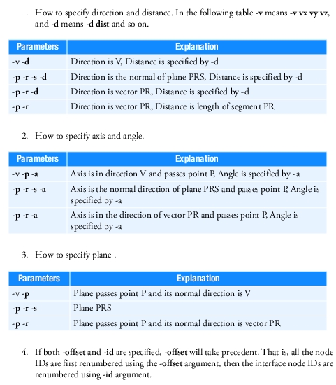 |
Examples:
1. mnfxform.exe -m input.mnf output.mnf -v 1 0 0 -p 0 0 0 -offset 1
This example mirrors input.mnf about yz plane and increase the ids of the interface nodes by 1. Then the transformed flexible body is saved as output.mnf.
2. mnfxform.exe -r input.MASTER::3 output.MASTER -p 1 0 0 -r 0 1 0 -s 0 0 1 -a 30 -id 5 10 11 12 13 14
This example rotates the 3rd flexible body in input.MASTER normal direction of plane PRS (defined by three points) by 30 degree (anti-clockwise). Then the first five interface node ids are renumbered to (10, 11, 12, 13, 14). Finally the transformed flexible body is saved to MD DB output.MASTER. If output.MASTER exists, the transformed body will be appended to it.
Limitation:
■For translation, rotation about an axis not passing origin or mirroring about a plane not passing origin, nodal mass and mode shape data is required to compute Invar4.
Converting Abaqus Input Files
To convert Abaqus input files into MSC Nastran input files use the command Abq2Nas. This is implemented within the Adams Flex toolkit command line. The exported MSC Nastran input files are written as SOL400 models. These can be used, for example, as input BDFs to Adams Flex Nonlinear.
Abq2Nas Usage
Following is the usage of the Abq2Nas command under flextk:
abq2nas <input_abaqus_file> <output_nastran_file> [direct_text_inputs]
Following are explanation of the arguments.
Argument: | Description: |
|---|---|
<input_abaqus_file> | Abaqus input file name. |
<output_nastran_file> | MSC Nastran BDF file name. The translation processing information including warnings and errors will be written to a log file named as the prefix of BDF with “.abq2nas” extension. |
[direct_text_inputs] | Optional arguments for setting text inputs directly to step, case control and bulk data sections. Below is are examples of the options: abq2nas aa.inp bb.bdf CASE=“NLOPRM NLDBG=NRDBG” abq2nas aa.inp bb.bdf STEP=“AUTOSPC(RESIDUAL,PUNCH)=YES” abq2nas aa.inp bb.bdf BULK=“NLMOPTS,LRGS,1;,,SPROPMAP,2” Multiple lines can be expressed by using semicolons “;”, it is user’s responsibility to provide a correct MSC Nastran entry, the translator just takes it as is. Another option mergecontact=yes/no controls contact merging, which will be explained later. abq2nas aa.inp bb.bdf mergecontact=yes |
Supported entities and the map
The following shows the supported entities and how they map from Abaqus 2014 to MSC Nastran.
Notice here that “activate hyperelements formulation” is achieved by adding the card shown below into the MSC Nastran file:
NLMOPTS LRGSTRN 2
Abaqus | MSC Nastran |
|---|---|
Plane Strain | |
CPE3 | CTRIA3, PLPANE, PSHLN2 |
CPE3H | CTRIA3, PLPANE, PSHLN2 |
CPE4 | CQUAD4, PLPLANE + PSHLN2 |
CPE4H | CQUAD4, PLPLANE + PSHLN2, activate hyperelasticity formulation |
CPE4I | CQUAD4, PLPLANE + PSHLN2 |
CPE4IH | CQUAD4, PLPLANE + PSHLN2, activate hyperelasticity formulation |
CPE4R | CQUAD4, PLPLANE + PSHLN2 |
CPE4RH | CQUAD4, PLPLANE + PSHLN2, activate hyperelasticity formulation |
CPE6 | CTRIA6, PLPLANE + PSHLN2 |
CPE6H | CTRIA6, PLPLANE + PSHLN2, activate hyperelasticity formulation |
CPE6M | CTRIA6, PLPLANE + PSHLN2 |
CPE6MH | CTRIA6, PLPLANE + PSHLN2, activate hyperelasticity formulation |
CPE8 | CQUAD8, PLPLANE + PSHLN2 |
CPE8H | CQUAD8, PLPLANE + PSHLN2, activate hyperelasticity formulation |
CPE8R | CQUAD8, PLPLANE + PSHLN2 |
CPE8RH | CQUAD8, PLPLANE + PSHLN2, activate hyperelasticity formulation |
Plane Stress | |
CPS3 | CTRIA3, PLPLANE + PSHLN2 |
CPS4 | CQUAD4, PLPLANE + PSHLN2 |
CPS4I | CTRIA3, PLPLANE + PSHLN2 |
CPS4R | CTRIA3, PLPLANE + PSHLN2 |
CPS6 | CTRIA6, PLPLANE + PSHLN2 |
CPS6M | CTRIA6, PLPLANE + PSHLN2 |
CPS8 | CQUAD8, PLPLANE + PSHLN2 |
CPS8R | CQUAD8, PLPLANE + PSHLN2 |
Generalized Plane Strain | |
CPEG3 | CTRIA3, PLPLANE + PSHLN2 |
CPEG3H | CTRIA3, PLPLANE + PSHLN2 |
CPEG4 | CQUAD4, PLPLANE + PSHLN2 |
CPEG4H | CQUAD4, PLPLANE + PSHLN2, activate hyperelasticity formulation |
CPEG4I | CQUAD4, PLPLANE + PSHLN2 |
CPEG4IH | CQUAD4, PLPLANE + PSHLN2, activate hyperelasticity formulation |
CPEG4R | CQUAD4, PLPLANE + PSHLN2 |
CPEG4RH | CQUAD4, PLPLANE + PSHLN2, activate hyperelasticity formulation |
CPEG6 | CTRIA6, PLPLANE + PSHLN2 |
CPEG6H | CTRIA6, PLPLANE + PSHLN2, activate hyperelasticity formulation |
CPEG6M | CTRIA6, PLPLANE + PSHLN2 |
CPEG6MH | CTRIA6, PLPLANE + PSHLN2, activate hyperelasticity formulation |
CPEG8 | CQUAD, PLPLANE + PSHLN2 |
CPEG8H | CQUAD, PLPLANE + PSHLN2, activate hyperelasticity formulation |
CPEG8R | CQUAD, PLPLANE + PSHLN2 |
CPEG8RH | CQUAD, PLPLANE + PSHLN2, activate hyperelasticity formulation |
Axisymmetric, Stress/displacement elements without twist | |
CAX3 | CTRIAX, PLPLANE + PSHLN2 |
CAX3H | CTRIAX, PLPLANE + PSHLN2, activate hyperelasticity formulation |
CAX4 | CQUADX, PLPLANE + PSHLN2 |
CAX4H | CQUADX, PLPLANE + PSHLN2, activate hyperelasticity formulation |
CAX4I | CQUADX, PLPLANE + PSHLN2 |
CAX4IH | CQUADX, PLPLANE + PSHLN2, activate hyperelasticity formulation |
CAX4R | CTRIAX, PLPLANE + PSHLN2 |
CAX4RH | CQUADX, PLPLANE + PSHLN2, activate hyperelasticity formulation |
CAX6 | CTRIAX, PLPLANE + PSHLN2 |
CAX6H | CTRIAX, PLPLANE + PSHLN2, activate hyperelasticity formulation |
CAX6M | CTRIAX, PLPLANE + PSHLN2 |
CAX8 | CQUADX, PLPLANE + PSHLN2 |
CAX8H | CQUADX, PLPLANE + PSHLN2, activate hyperelasticity formulation |
CAX8R | CQUADX, PLPLANE + PSHLN2 |
CAX8RH | CQUADX, PLPLANE + PSHLN2, activate hyperelasticity formulation |
Axisymmetric, Stress/displacement elements with twist | |
CGAX3 | CTRIAX, PLPLANE + PSHLN2 |
CGAX3H | CTRIAX, PLPLANE + PSHLN2, activate hyperelasticity formulation |
CGAX4 | CQUADX, PLPLANE + PSHLN2 |
CGAX4H | CQUADX, PLPLANE + PSHLN2, activate hyperelasticity formulation |
CGAX4R | CQUADX, PLPLANE + PSHLN2 |
CGAX4RH | CQUADX, PLPLANE + PSHLN2, activate hyperelasticity formulation |
CGAX6 | CTRIAX, PLPLANE + PSHLN2 |
CGAX6H | CQUADX, PLPLANE + PSHLN2, activate hyperelasticity formulation |
CGAX6M | CTRIAX, PLPLANE + PSHLN2 |
CGAX6MH | CTRIAX, PLPLANE + PSHLN2, activate hyperelasticity formulation |
CGAX8 | CTRIAX, PLPLANE + PSHLN2 |
CGAX8H | CQUADX, PLPLANE + PSHLN2 |
CGAX8R | CQUADX, PLPLANE + PSHLN2, activate hyperelasticity formulation |
CGAX8RH | CQUADX, PLPLANE + PSHLN2 |
3D Stress/displacement elements | |
C3D4 | CTETRA, PSOLID + PSLDN1 |
C3D4H | CTETRA, PSOLID + PSLDN1 |
C3D6 | CPENTA, PSOLID + PSLDN1 |
C3D6H | CPENTA, PSOLID + PSLDN1, activate hyperelasticity formulation |
C3D8 | CHEXA, PSOLID + PSLDN1 |
C3D8H | CHEXA, PSOLID + PSLDN1, activate hyperelasticity formulation |
C3D8I | CHEXA, PSOLID + PSLDN1 |
C3D8IH | CHEXA, PSOLID + PSLDN1, activate hyperelasticity formulation |
C3D8R | CHEXA, PSOLID + PSLDN1 |
C3D8RH | CHEXA, PSOLID + PSLDN1, activate hyperelasticity formulation |
C3D10 | CTETRA, PSOLID + PSLDN1 |
C3D10H | CTETRA, PSOLID + PSLDN1, activate hyperelasticity formulation |
C3D10I | CTETRA, PSOLID + PSLDN1 |
C3D10M | CTETRA, PSOLID + PSLDN1 |
C3D10MH | CTETRA, PSOLID + PSLDN1, activate hyperelasticity formulation |
C3D15 | CPENTA, PSOLID + PSLDN1 |
C3D15H | CPENTA, PSOLID + PSLDN1, activate hyperelasticity formulation |
C3D20 | CHEXA, PSOLID + PSLDN1 |
C3D20H | CHEXA, PSOLID + PSLDN1, activate hyperelasticity formulation |
C3D20R | CHEXA, PSOLID + PSLDN1 |
C3D20RH | CHEXA, PSOLID + PSLDN1, activate hyperelasticity formulation |
Membrane | |
M3D3 | CTRIA3, PSHELL |
M3D4 | CQUAD4, PSHELL |
M3D4R | CQUAD4, PSHELL |
M3D6 | CTRIA6, PSHELL |
M3D8 | CQUAD8, PSHELL |
M3D8R | CQUAD8, PSHELL |
M3D9 | CQUAD8, PSHELL |
M3D9R | CQUAD8, PSHELL |
2D truss | |
T2D2 | CROD, PROD |
T2D2H | CROD, PROD/PRODN1 |
T2D3 | CROD, PROD |
T2D3H | CROD, PROD/PRODN1 |
3D truss | |
T3D2 | CROD, PROD |
T3D2H | CROD, PROD |
T3D3 | CROD, PROD |
T3D3H | CROD, PROD |
Beam in plane | |
B21 | CBEAM, PBEAM/PBEAML |
B21H | NA, but write out the same one as B21 with a warning |
B22 | CBEAM3, PBEAM/PBEAML |
B22H | NA, but write out the same one as B22 with a warning |
B23 | NA, but write out the same one as B21 with a warning |
B23H | NA, but write out the same one as B21 with a warning |
Beam in 3D space | |
B31 | CBEAM, PBEAM/PBEAML |
B31H | NA, but write out the same one as B31 with a warning |
B32 | CBEAM3, PBEAM/PBEAML |
B32H | NA, but write out the same one as B32 with a warning |
B33 | NA, but write out the same one as B31 with a warning |
B33H | NA, but write out the same one as B31 with a warning |
Conventional shells | |
STRI3 | CTRIA3, PSHELL |
S3 | CTRIA3, PSHELL |
S3R | CTRIA3, PSHELL + PSHLN1 |
S3RS | CTRIA3, PSHELL + PSHLN1 |
STRI65 | CTRIA3, PSHELL |
S4 | CQUAD4, PSHELL |
S4R | CQUAD4, PSHELL + PSHLN1 |
S4RS | CQUAD4/PSHELL + PSHLN1 |
S4RSW | CQUAD4/PSHELL + PSHLN1 |
S4R5 | CQUAD4/PSHELL + PSHLN1 |
S8R | CQUAD8/PSHELL + PSHLN1 |
S8R5 | CQUAD8/PSHELL + PSHLN1 |
Continuum shell(Solid shell) | |
SC8R | CHEXA, PCOMPLS |
Spring | |
SPRINGA | CBUSH, PBUSH + PBUSHT |
SPRING1 | CELAS1, PELAS + PELAST |
SPRING2 | CBUSH, PBUSH + PBUSHT |
Dashpot | |
DASHPOT1 | CBUSH, PBUSH + PBUSHT |
DASHPOT2 | CBUSH, PBUSH + PBUSHT |
DASHPOTG | CBUSH, PBUSH + PBUSHT |
Flexible joint | |
JOINTC | CBUSH, PBUSH + PBUSHT |
Distributing coupling | |
DCOUP2D | RBE2/RBE3 |
DCOUP3D | RBE2/RBE3 |
Gasket | |
GK3D8 | CHEXA, PSOLID, MATG |
GK3D8N | CHEXA, PSOLID, MATG |
Other geometry entities | |
*NGEN | GRID |
*NFILL | GRID |
*ELGEN | Elements |
*ASSEMBLY/*INSTANCE/*PART | offset ids of GRID and elements, *ELSET or *NSET with option INSTANCE=part_name is available also |
*SYSTEM | CORD2R and write the cord2r id to CP field of related GRID |
*ORENTATION | CORD2R and write the cord2r id to CBUSH, COMN1, 2D elements, shell elements and PSOLID |
*TRANSFORM | CORD2R and write the cord2r id to CD field of related GRID |
Properties | |
*SOLID SECTION | PSOLID |
*SHELL SECTION | PSHELL/PCOMP/PCOMPL/PCOMPLS |
*BEAM SECTION | PBEAM/PBEAML |
*BEAM GENERAL SECTION | PBEAML |
*GASKET SECTION | MATG |
Materials | |
*ELASTIC | MAT1/MAT8/MATORT/MAT9 |
*DENSITY | Å@ |
*PLASTIC | MATEP |
*HYPERELASTIC | MATHE |
*VISCOELASTIC | MATVE |
*CREEP | MATVP |
Contact | |
*SURFACE | BCBODY1,BSURF, BCNURB2, BCPATCH depending on *RIGID BODY |
*RIGID BODY | BCNURB2 for analytical curves, a BCPACH for 3D model when the elements used by a *SURFACE |
*CONTACT PAIR | BCONNECT |
*SURFACE INERACTION | BCONPRP |
*TIE | Glue contact (BCONNECT) |
Loads Boundaries | |
*CLOAD | FORCE/MOMENT |
*TEMPERATUE | TEMP |
*INTIAL CONDITION TYPE=TEMPERATUE | TEMP and TEMPERATURE(INIT) in case control |
*DLOAD | PLOAD4/PLOAD1 GRAV RFORCE PLOADX |
*DSLOAD | PLOAD4 for shell and solid, PLOAD1for beam elements PLOADX |
MPC, Coupling and so on. | |
*Kinematic Coupling | RBE2 |
*Distributing Coupling | RBE3 |
*Coupling + *Kinematic | RBE2 |
*Coupling + *Distributing | RBE3 |
*MPC Beam type | RBAR |
*Pre-tension | BOLT |
*Equation | MPC |
Analysis procedure | |
*STATIC, Perturbation | ANALYSIS=STATIC |
*STATIC, no perturbation | ANALYSIS=NLSTATIC |
*Frequency | ANALYSIS=MODES |
In contact area, there is a strict limitation in MSC Nastran: one element can only be used by one contact body; the translator is highly possibly to make an element belong to multiple bodies. To overcome this issue, merging contact bodies that share common elements into one body is required. Command line option mergecontact=yes/no will control this, the default is yes, no will be provided for debugging purpose.
Important known limitations
The following input syntax is known to be not supported. This is not necessarily a complete list:
*AMPLITUDE
*BULK VISCOSITY
*CONTACT
*CONTACT INCLUSION
*CONTACT PAIR is not completely supported
*CONTACT PROPERTY ASSIGNMENT
*CYCLIC HARDENING
*DISTRIBUTION
*DLOAD - several parameters including PY are not supported
*DRUCKER PRAGER
*DRUCKER PRAGER HARDENING
*DSLOAD – several parameters including HP are not supported
*DYNAMIC
*FRAME SECTION, also B33 element is not supported
*HYPERELASTIC – parameter MODULI AND POLYNOMIAL
*INITIAL CONDITIONS type HARDENING
*INITIAL CONDITIONS type STRESS
*MOHR COULOMB
*MOHR COULOMB HARDENING
*MPC – type C BIQUAD and QUADRATIC are not supported
*NCOPY
*PLASTIC, DEPENDENCIES
*RBE - only 1D analytical surfaces and 2D R3D4, R3D3 elements can be translated
*REBAR LAYER
*STEADY STATE DYNAMICS
*STEP – parameter UNSYMM
*SUBMODEL
*SURFACE BEHAVIOR
*SURFACE is not completely supported
*SWELLING
*VISCO
BEH4 and BEH8 are not supported
Generalized plane strain elements are translated into equivalent plane strain elements
Recovering Flexible Body Deformation
MNFRES is a tool to recover the nodal displacement, velocity and acceleration of a flexible body after a simulation.
MNFRES Usage
Following is the usage of the mnfres command under flextk:
mnfres [options] <Adams_result_file> <input_flex_file>
Argument: | Description: | |
|---|---|---|
[option] | -t <time> or | output results only till specified time |
<tms,tme> | output results at the times <tms> to <tme> | |
-n <name> | specify flexible body when multiple exist | |
-g | include rigid body motion | |
-r | also report nodal rotations. Only effective when -g is not specified | |
-s <file> | report only on nodes listed in <file> | |
-L <unit> | specify length unit used in the Adams model, e.g.,METER,INCH, FOOT, MILE, MILLIMETER,CENTIMETER, KILOMETER. Abbreviation is accepted. Default value is METER. | |
-T <unit> | specify time unit used in the Adams model, e.g.,SECOND, MILLISECOND, DAY, HOUR, MINUTE. Default value is SECOND. Abbreviation is accepted. | |
-i <key> | report specific results. <key> values are: d : Nodal displacements v : Nodal velocities a : Nodal accelerations | |
<Adams_result_file> | Adams result file. | |
<input_flex_file> | Modal Neutral File or MD DB File. MD DB File is in the form of foo.MASTER[::#], foo.MASTER is the database and # is the index of the body. For example, foo.MASTER::2 indicates the second flexible body in foo.MASTER. foo.MASTER, without ::#, indicates the first flexible body. | |
Notes: | 1. If -g option is not specified, the output value is in flexbody PBCS. If specified, the output is with respect to ground. 2. By default the output result use METER and SECOND. So if the length unit used in the Adams model is not METER, you must specify -L <unit> option in order to get correct results. Same is true for time unit. 3. By default, the output will be printed to screen. User can use > filename to redirect the output to a file. |
Examples:
1. mnfres -i d -n FLEX_BODY_1 example.res foo.mnf
Output all the nodal deformation of flexible body FLEX_BODY_1, whose mnf file is foo.mnf and the result file is example.res.
2. mnfres -i d -n FLEX_BODY_1 example.res foo.mnf > out.dat
Redirect the output in example 1 to out.dat.
3. mnfres -i v -L MM -g -n FLEX_BODY_3 example.res foo.MASTER::2
Output all the nodal velocity of flexible body FLEX_BODY_3, which is the second flexible body stored in MD DB file, foo.MASTER, using result file example.res. The velocity includes rigid motion and the length unit is MILLIMETER.
Editing an MNF or an MD DB
MNF2MTX allows you to edit the interface (ASET) node coordinates or generalized mass/stiffness of an existent MNF or MD DB.
MNF2MTX Usage
Following is the usage of the mnf2mtx command under flextk:
mnf2mtx <input_flex_file> -O <output_flex_file> [-I id1,x1,y1,z1,id2,x2,y2,z2,...,idn,xn,yn,zn]
[-mscale scale_factor] [-sscale scale_factor]
Argument: | Description: |
|---|---|
<input_flex_file> | Input Modal Neutral File or MD DB File. MD DB File is in the form of foo.MASTER[::#], foo.MASTER is the database and # is the index of the body. For example, foo.MASTER::2 indicates the second flexible body in foo.MASTER. foo.MASTER, without ::#, indicates the first flexible body. |
<output_flex_file> | Output Modal Neutral File or MD DB File. MD DB File is in the form of foo.MASTER[::#], foo.MASTER is the database and # is the index of the body. For example, foo.MASTER::2 indicates the second flexible body in foo.MASTER. foo.MASTER, without ::#, indicates the first flexible body. |
[-I id1,x1,y1,z1,...] | Optional argument to specify interface node coordinates to be edited. id* are the interface node IDs, and x*, y* and z* are the modified coordinates. IDs must be existed in the flex file and 4 parameters must be specified per 1 interface node. This option affects the interface node coordinate only. |
[-mscale scale_factor] | Optional argument to specify scale factor of generalized mass. The scale factor affects the generalized mass and all eigenvalues are divided by the factor. In addition, nodal mass/inertia are multiplied by the factor. Note that scaled modal masses are normalized (reverted to 1.0) during flex file exportation and then eigenvectors are divided by square root of the factor. As a result, mass invariant matrices are scaled like as follows. INVAR1, INVAR2, INVAR7: Multiplied by the factor INVAR3, INVAR4, INVAR8: Multiplied by square root of the factor |
[-sscale scale_factor] | Optional argument to specify scale factor of generalized stiffness. The scale factor affects the generalized stiffness and all eigenvalues are multiplied by the factor. In addition, mode stress values are also multiplied by the factor if exists. |
Examples:
1. mnf2mtx.exe input.mnf -O output.MASTER -I 11,0.0,0.5,10.0,121,1.0,0.75,15.0
This example edits input.mnf for the coordinates of interface node 11 and 121 to X=0.0, Y=0.5 and Z=10.0 and X=1.0, Y=0.75 and Z=15.0 respectively. The edited flexible body is saved to MD DB output.MASTER. If output.MASTER exists, the edited flexible body will be appended to it.
2. mnf2mtx.exe input.MASTER::3 -O output.mnf -mscale 1.2 -sscale 0.8
This example edits the 3rd flexible body in input.MASTER to scale generalized mass with the factor of 1.2 and scale generalized stiffness with the factor of 0.8. The edited flexible body is saved as output.mnf.