Specifying Damping
Several types of damping are inherently present in mechanical systems. Understanding the source and level of damping are important in the simulation and testing of dynamic systems. For example, a mechanism having low natural frequencies and relatively low damping, could produce damaging motions under resonant conditions.
Applying damping judiciously can also improve simulation performance for models containing flexible bodies. For example, consider a flexible body with a 10 kHz mode whose shape is considered essential to allowing the body to assume a particular deformation. Any response in this mode at its resonant frequency dictates integration steps on the order of 1E-5 seconds, which can be unacceptable for long duration simulations. If the damping for this mode is set at 100% of critical damping, however, any resonant response is immediately suppressed. The mode's compliance is retained but its dynamics are eliminated and the simulation performance is improved.
Learn more:
Damping Dissipation and Damping Matrix
The damping force on a flexible body is proportional to its generalized velocities and is assumed to be derivable from the quadratic form:

where:
D | is a symmetric matrix of damping coefficients |
 | is a vector of generalized velocities: |
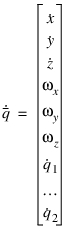 |
■ are the absolute time derivatives of the position vector coordinates of the local part reference frame with respect to the local part reference frame.
are the absolute time derivatives of the position vector coordinates of the local part reference frame with respect to the local part reference frame.■ are the angular velocity vector coordinates with respect to the local part reference frame.
are the angular velocity vector coordinates with respect to the local part reference frame. ■ are the time derivatives of the modal coordinates.
are the time derivatives of the modal coordinates.The matrix D is composed of two parts, Dm and Dg:

Dm represents the contribution of proportional modal damping, and Dg represents the contribution of a generalized damping matrix. Both are explained in the next section.
Specifying Modal Damping
The modal damping matrix Dm is diagonal and defined using critical damping ratios  for each mode i= 1,n.
for each mode i= 1,n.
where  and
and  are the generalized stiffness and mass for mode i.
and are the generalized stiffness and mass for mode i. Note: | The damping ratio  does not need to be constant. It can be a function of time or system state. does not need to be constant. It can be a function of time or system state. |
If you do not specify modal damping when you create the flexible body, Adams Flex applies a default, non-zero critical damping ratio as follows:
■1% damping for all modes with frequency lower than 100.
■10% damping for modes with frequency in the 100 to 1000 range.
■100% critical damping for modes with frequency above 1000.
You can change the default modal damping in three ways:
■Assign a single scalar critical damping ratio that Adams Flex applies uniformly to all modes.
■Enter Adams run-time function expressions to create complex damping phenomena in your flexible body. In addition, function expressions, such as FXFREQ and FXMODE, allow you to apply different levels of damping to individual modes.
■Control the damping using the DMPSUB user-written subroutine. DMPSUB lets you set different levels of damping for different modes and the damping can vary over time. For more on writing subroutines, see the Subroutines section of the Adams Solver online help.
To assign modal damping when creating or modifying a flexible body:
1. In either the Create a Flexible Body dialog box or Flexible Body Modify dialog box, clear the selection of default (use default in the Create a Flexible Body dialog box).
2. In the Damping Ratio text box, either:
■Enter the critical damping ratio.
■Enter a function. To get help building the function, next to the Damping Ratio text box, select the More button  . The Adams View Function Builder appears. For information on using the Function Builder, see the Adams View Function Builder online help.
. The Adams View Function Builder appears. For information on using the Function Builder, see the Adams View Function Builder online help. 3. Continue creating or modifying the body, and then select OK.
Specifying Generalized Damping
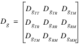
The generalized damping matrix Dg is a constant symmetric matrix of the form:
To better understand how the generalized damping matrix is handled in Adams Flex, it is helpful to start with the discrete finite element equations of motion:
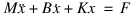
where:
■M, K, and B are the finite element mass, stiffness, and damping matrices, respectively ■x is the nodal coordinate vector ■F is the applied force vector |
The damping matrix B is derived from damping elements and parameters defined in the finite element model. The previous equation can be transformed into modal coordinates:
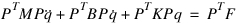
where P is the matrix of mode shapes stored column-wise and q is the vector of modal coordinates. PTBP represents the generalized damping matrix. However, before Adams Flex can use the generalized damping matrix, the portion of PTBP that projects onto the rigid body modes must be transformed to the nonlinear, large motion, generalized coordinates: X, Y, Z,  ,
,  , and
, and  used to represent the flexible body’s large overall motion in Adams Solver (C++). To this end, a m x 6 transformation matrix, A, is constructed and transforms m rigid body modes to the six coordinates X, Y, Z,
  ,
,  , and
, and  , and the final generalized matrix Dg is computed:
, , and used to represent the flexible body’s large overall motion in Adams Solver (C++). To this end, a m x 6 transformation matrix, A, is constructed and transforms m rigid body modes to the six coordinates X, Y, Z, , , and , and the final generalized matrix Dg is computed: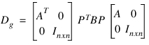
If the damping description in the finite element model results in a resultant damping force, there will be nonzero entries in the sub-matrices 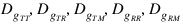 . Because the resultant damping force was derived from a linear finite element model governed by small strain approximations and infinitesimal rotations, a resultant damping force may yield unexpected results in the context of large overall motion supported in Adams. Therefore, Adams Flex provides the option to ignore the resultant damping force. Ignoring a resultant damping force is referred to as internal-only generalized damping.
. Because the resultant damping force was derived from a linear finite element model governed by small strain approximations and infinitesimal rotations, a resultant damping force may yield unexpected results in the context of large overall motion supported in Adams. Therefore, Adams Flex provides the option to ignore the resultant damping force. Ignoring a resultant damping force is referred to as internal-only generalized damping.Because the generalized matrix Dg is derived from the component finite element model, you can leverage the damping elements and features in the finite element program. This is particularly useful for defining non-proportional and spatially-dependent damping. Furthermore, the generalized damping matrix is stored in the MNF to be optionally applied to the flexible body. That is, because you defined damping in the finite element model, it is not necessary to employ it in Adams. To enable generalized damping, however, you must have a generalized damping matrix stored in your MNF.
To specify generalized damping when creating or modifying a flexible body:
1. In either the Create a Flexible Body dialog box or Flexible Body Modify dialog box, set Generalized Damping to:
■Off - Disables the generalized damping.
■Full - Enables the complete generalized damping matrix, including the effects of a resultant damping force.
■Internal Only - Only enables the portion of the generalized damping matrix corresponding to the modal coordinates (that is, ignore the resultant damping force).
2. Continue creating or modifying the body, and then select OK.