Damping
The damping tab allows one to modify various damping settings on the nonlinear flexible body. At simulation time when Adams View prepares the run-ready flexible body data deck, the DAMPING card field names shown on the dialog will be updated with the values shown on the dialog. Be sure to use units consistent with the units set of the flexible body listed at the top of the dialog since the run-ready flexible body data deck will use those units as opposed to the units of the Adams View session which are not required to match.
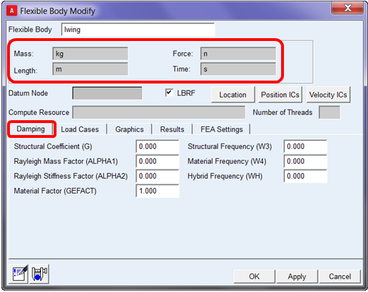
These damping parameters are explained in the dialog box help accessible by pressing the F1 key from anywhere within the dialog.
Damping for the linear (MNF-based) flexible body is done on a modal basis since those flexible bodies are essentially a superposition of individual modes. Since the nonlinear flexible body is not such a simplification from FEA but, rather, more like an FE model directly embedded in the Adams model, the damping definition is fundamentally different and applied directly to the body itself, primarily as structural and Rayleigh damping. More details about defining structural and Rayleigh damping are described below:
Structural Damping
Setting values in the "Damping" tab (shown above) will instruct Adams View and Adams Car to add parameters to the run-ready MSC Nastran data deck (.dat) exported at analysis time. Specifically for structural damping the following can be used:
Elemental Structural Damping:
■Material Frequency (W4)
■Card in .dat file = PARAM, W4
■This is the frequency of interest in radians per unit time for conversion of element structural damping into equivalent viscous damping. The user would need to specify GE as required on the MATi entry for element specific structural damping.

Overall Structural Damping:
■Structural Coefficient (G) and Structural Frequency (W3)
■Cards in .dat file: PARAM, G and PARAM, W3
■G is the overall structural damping coefficient. To get G, multiply the critical damping ratio by two
■W3 is the frequency of interest in radians per unit time (PARAM,W3) for the conversion of overall structural damping into equivalent viscous damping
Structural damping would be represented as viscous damping for transient analysis. The damping matrix in this case would be proportional to the stiffness matrix [K] (this applied to both linear and nonlinear/tangent stiffness).
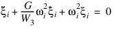
First we'll see the effect overall structural damping coefficient, G, and frequency W3. EOM of linearized (unforced system):
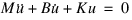
The damping matrix is represented as  , Hence, above equation becomes,
, Hence, above equation becomes,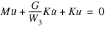
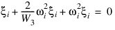
We can easily, see, the effect if we transform to uncoupled modal coordinates (using the mass normalized modal matrix,
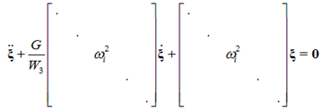
Looking at a single modal coordinate,
G is two times the critical damping ratio. For example, if want the mode at W3 to be critically damped, then set G = 2.0. In such a case we'll have,
For,  , the above system is under-damped
, the above system is under-dampedFor,  , the system,
 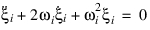 , is critically-damped
, the system, , is critically-dampedFor,  , the above system is over-damped
, the above system is over-dampedThe effect of structural damping coefficients, GE, and frequency W4 are similar except they act on elemental stiffness and the damping matrix due to these is given by 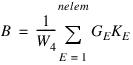
Rayleigh Damping
Setting values in the "Damping" tab (shown above) will instruct Adams View and Adams Car to add parameters to the run-ready MSC Nastran data deck (.dat) exported at analysis time. Specifically for Rayleigh damping the following can be used:
■Rayleigh Mass Factor (ALPHA1) and Rayleigh Stiffness Factor (ALPHA2)
■Cards in .dat file = PARAM, ALPHA1 and PARAM, ALPHA2
■In transient response analysis, if PARAM, ALPHA1 and/or ALPHA2 are not equal to zero, then Rayleigh damping is added to the viscous damping. ALPHA1 is the scale factor applied to the mass matrix and ALPHA2 to the structural stiffness matrix.
Rayleigh damping is specified as:
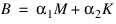
It allows user to select two damping ratios,  for known modes having natural frequencies
  respectively. With these parameters know, the parameters
  can be calculated with:
for known modes having natural frequencies respectively. With these parameters know, the parameters can be calculated with: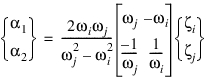
The damping ratio,  , of any other mode at
  , is given by:
, of any other mode at , is given by: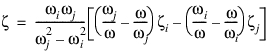
Below is a plot of damping ratio Vs natural frequency for a particular set of parameters shown in the plot.
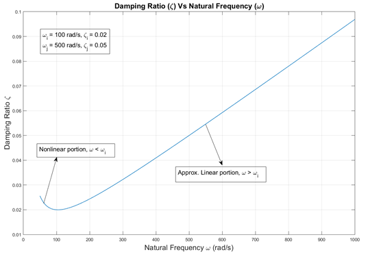
Although Rayleigh damping achieves the objective of having higher damping for modes at higher frequency, one can see that the damping ratio  is not as well-behaved and may not be intended by the Adams user solving multibody dynamics problems characterized by large rigid body motion.
is not as well-behaved and may not be intended by the Adams user solving multibody dynamics problems characterized by large rigid body motion.